Eureka AIR delivers breakthrough ideas for toughest innovation challenges, trusted by R&D personnel around the world.

Conical slit-type hot end heat exchanger of coaxial pulse tube refrigerator and manufacturing method

A technology of pulse tube refrigerator and coaxial type, which is applied in refrigerators, indirect heat exchangers, gas circulation refrigerators, etc., and can solve problems such as difficult process, failure to meet heat dissipation requirements, and large heat exchanger losses.

Active Publication Date: 2012-10-17
SHANGHAI INST OF TECHNICAL PHYSICS - CHINESE ACAD OF SCI
View PDF6 Cites 18 Cited by
  • Summary
  • Abstract
  • Description
  • Claims
  • Application Information

AI Technical Summary

Problems solved by technology

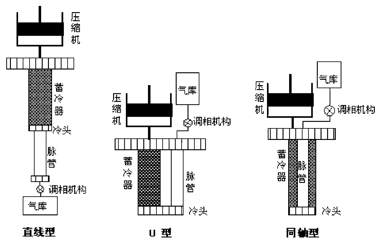
The three layout methods have their own advantages and disadvantages in practical application
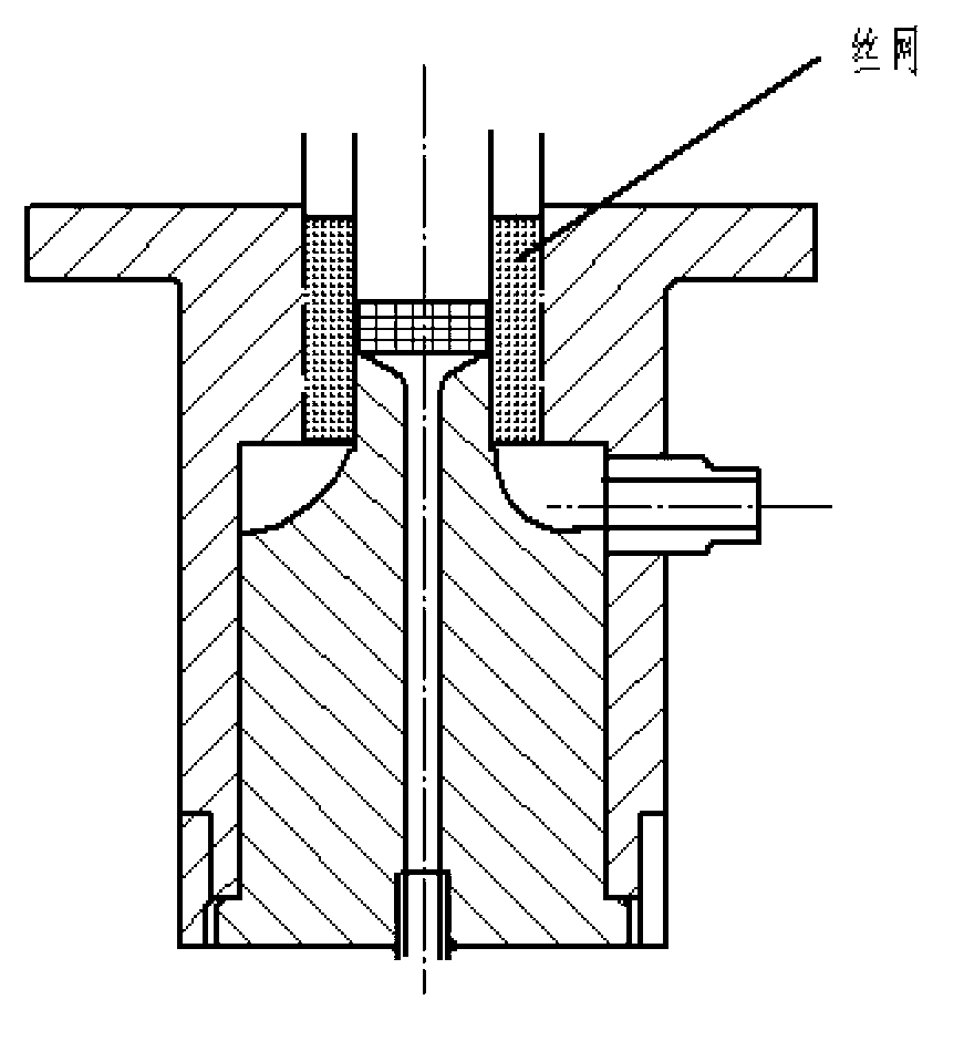
[0011] 1) The pressure drop is larger than that of the slit heat exchanger, and the loss through the hot end heat exchanger becomes larger;
[0012] 2) The wire mesh and the flange wall must be closely matched, which is difficult to achieve now;
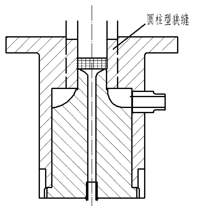
[0013] image 3 Although the conventional cylindrical slit-type hot-end heat exchanger shown can also exchange heat efficiently, due to the limitation of the hot-end flange structure, the heat exchange area of ​​the slit is limited, and often cannot meet the best heat dissipation requirements;
[0014] The above-mentioned many factors lead to the decline of the overall performance of the refrigerator, which is one of the key factors affecting the actual cooling efficiency of the coaxial pulse tube refrigerator and one of the important reasons hindering its practical application.

Method used


Image

  • Conical slit-type hot end heat exchanger of coaxial pulse tube refrigerator and manufacturing method
  • Conical slit-type hot end heat exchanger of coaxial pulse tube refrigerator and manufacturing method
  • Conical slit-type hot end heat exchanger of coaxial pulse tube refrigerator and manufacturing method

Examples


Embodiment Construction

[0031] Below in conjunction with accompanying drawing, the specific embodiment of this patent is described in further detail:

[0032] The hot-end tapered slit of the patented coaxial pulse tube refrigerator consists of three parts: the hot-end flange 7 , the tapered slit 1 and the hot-end plug 5 .

[0033] like Figure 5 As shown: the hot-end flange 7 and the hot-end air inlet 10 are connected by silver welding or brazing, and the inner wall surface 11 of the hot-end flange coincides with the outlet of the hot-end air inlet during welding. like Figure 7 As shown: the upper boss of the tapered slit heat exchanger 1 in the hot end flange 7 is smaller than the lower boss, and the radius of the tangential circle of the upper boss is equal to the outer diameter of the cold storage 2, and the tangential radius of the lower boss The radius of the circle is equal to the radius of the tangential circle of the hot end plug, and the inner diameter of the conical slit heat exchanger i...


PUM


Abstract

The invention discloses a conical slit-type hot end heat exchanger of a coaxial pulse tube refrigerator and a manufacturing method. The heat exchanger structurally consists of a hot end flange, a conical slit and a hot end plug, wherein the conical slit is inserted into the hot end flange in a tight fit way, the radius of a circle of contact on the top of a cone frustum is equal to the radius of a cold accumulator and the radius of the bottom of the cone frustum is equal to the radius of the hot end plug. The hot end plug and the hot end flange not only can be connected through bolts to form a detachable split-type hot end heat exchanger, but also can be hermetically welded to form an integrated hot end radiator. The conical slit-type hot end heat exchanger has the advantages that the structure is simple, compact and high-efficiency, the hot end radiating capacity of the refrigerator can be exerted to the utmost extent and the hot end pressure ratio of the pulse tube refrigerator is increased at the same time. The structure can intensively realize the major functions of a high-efficiency hot end heat exchanger, a hot end gas flow guide device of the pulse tube refrigerator and a hot end gas even distributor of the cold accumulator, and can improve the performance of the entire pulse tube refrigerator to a great extent.

Description

technical field [0001] The patent relates to a coaxial pulse tube refrigerator, in particular to a conical slit hot end heat exchanger and a manufacturing method of the coaxial pulse tube refrigerator. Background technique [0002] The pulse tube refrigerator was proposed by Gifford and Longsworth in the 1960s. In the mid-1980s, the efficiency and stability of the pulse refrigerator were greatly improved through the improvement of the phase adjustment mechanism at the hot end of the pulse refrigerator. It cancels the cold-end ejector widely used in Stirling or G-M machines, and replaces it with a pulse tube; instead of the cold-end ejector, it realizes the pressure wave required for refrigeration through the operation of the hot-end phasing mechanism Phase difference with mass flow. The pulse tube refrigerator can achieve low vibration, low interference and no wear at the cold end; the pulse tube refrigerator has been greatly developed in theory and experiment in the middle...

Claims


Application Information

Patent Timeline
Patent Type & Authority Applications(China)
IPC IPC(8): F28D21/00F25B9/14B23P15/26B23K1/00
CPCF25B2309/1406Y02P70/10
Inventor 杨开响吴亦农张安阔熊超张静夏梦颖
Owner SHANGHAI INST OF TECHNICAL PHYSICS - CHINESE ACAD OF SCI
Why Eureka
Eureka Blog
Learn More