Hollow blade of a ship propeller

A technology of hollow blades and propellers, which is applied in the direction of rotating propellers and rotary propellers, can solve the problems of not being able to reduce vibration and noise levels, and achieve the effect of reducing vibration and noise levels

Inactive Publication Date: 2011-05-04
FEDERALNOE GOSUDARSTVENNOE UNITARNOE PREDPRIYATIESANKT PETERBURGSKOE MORSKOE BYURO MACHINOSTROENIYA MALAKHIT
View PDF6 Cites 5 Cited by
  • Summary
  • Abstract
  • Description
  • Claims
  • Application Information

AI Technical Summary

Problems solved by technology

However, this structure of the propeller blade only provides for a symmetrical blade profile for reducing the weight of the blade structure, which does not reduce the vibration and noise levels originating from the propeller in a series of velocity field inhomogeneities from the incident flow operating under the conditions and the noise at the blade edge is not reduced, which occurs due to the vibration of the blade edge when the propeller is running

Method used


Image

  • Hollow blade of a ship propeller
  • Hollow blade of a ship propeller
  • Hollow blade of a ship propeller

Examples


Embodiment Construction

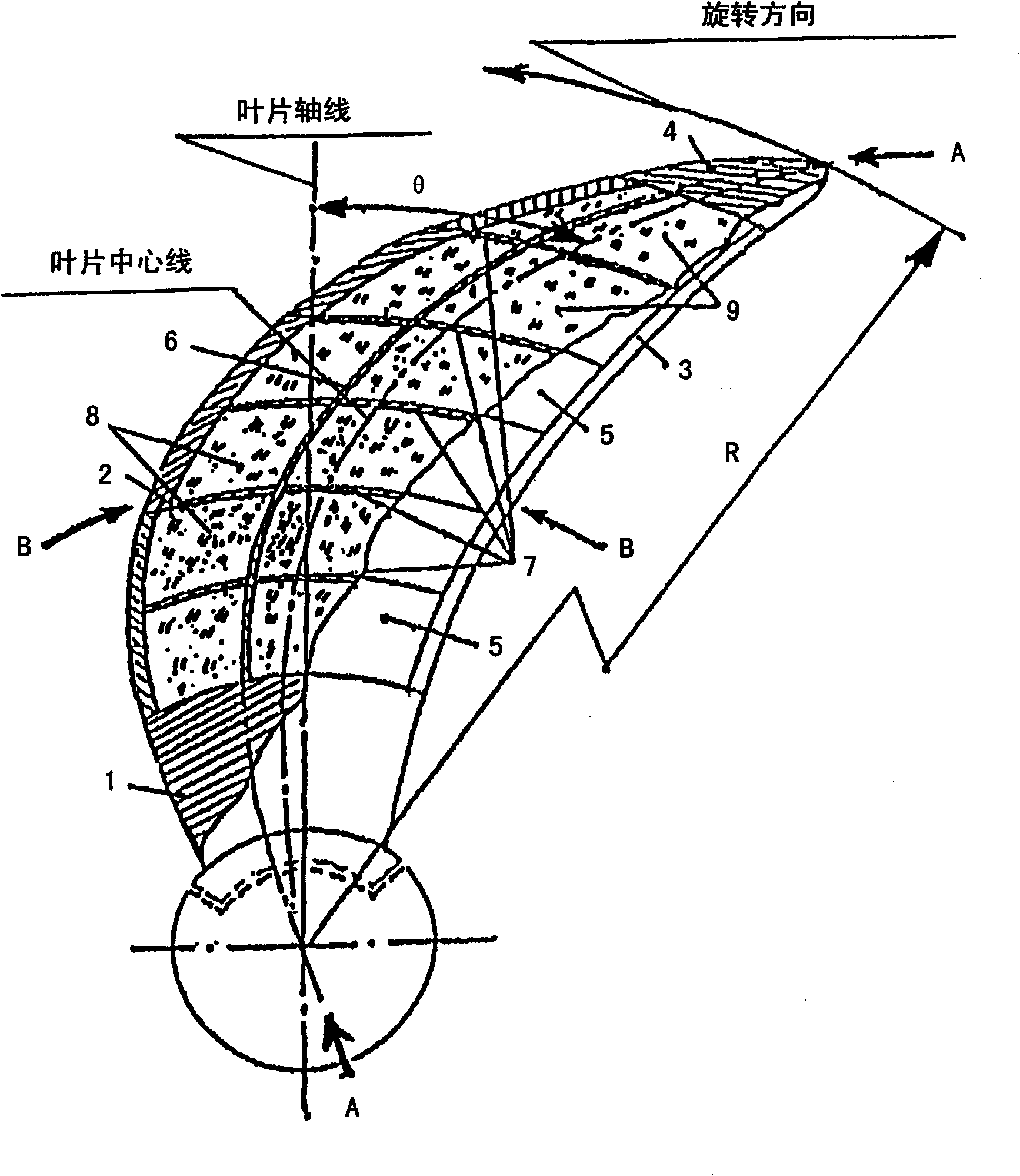
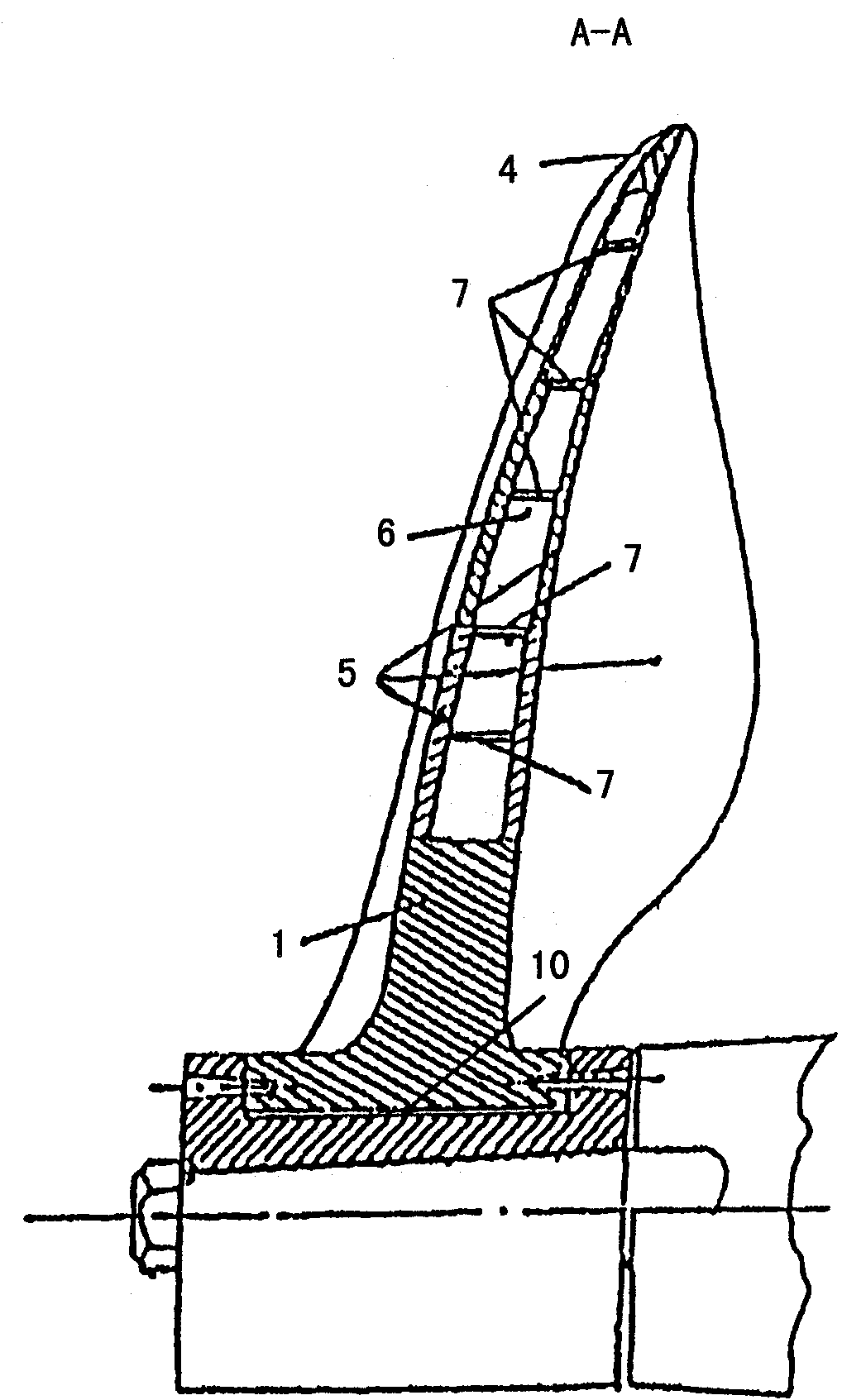
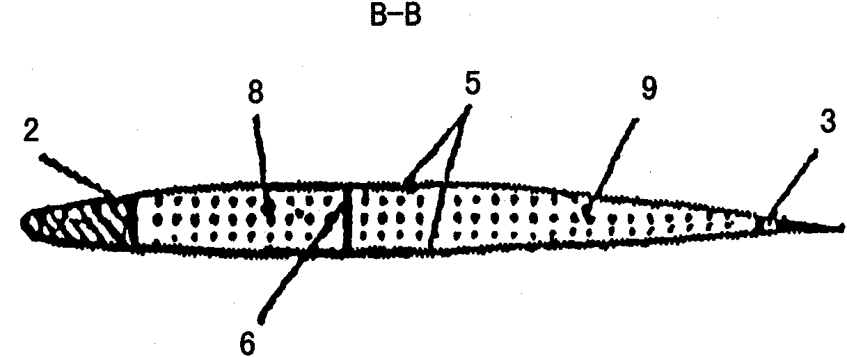
[0022] The blade comprises a root 1 which is cast for attachment to the hub and has a cast front wall 2 with an inlet edge and a rear wall 3 with an outlet edge, said walls being welded to the root and welded to the cast as one-piece-blade On top of the end (tip) 4 of the blade, thus forming the blade profile. The wall 2 of the inlet edge and the wall 3 of the outlet edge are connected between them by a casing 5 across said edges, forming the action (working) of the blades and the absorbing propeller surface ( figure 1 , 2) and a scimitar-shaped profile (the scimitar shape degree is 9).

[0023] The shape of the hollow blade with the selected scimitar shape is fixed from the outside by the casing and from the inside by the load-bearing structure, which forms a cast-welded structure, where the main load-bearing element of the structure is a strong longitudinal beam 6, which extends radially across the The entire span of the blade (along its length), is located at the profile p...


PUM


Abstract

The inventive hollow blade of a ship propeller comprises a top (4), a blade root (1), the walls of leading and exit edges which walls are interconnected by a plating (5) and form respectively the pressure and suction helicoidal surfaces and the blade outline, and an inner framework, wherein the hollow blade is scimitar-shaped and is cast-welded, the inner framework consists of a longitudinal load-bearing bar (6) and transversal load-bearing elements (7), the longitudinal load-bearing bar (6) is radially arranged in the cavities (8, 9) of the hollow blade along the length and the outline thereof, coinciding with the greatest thicknesses of the blade cross-sectional profile, and is welded to the blade top (4) by one end and to the blade root (1) by the other end, the transversal load-bearing elements (7) are disposed along the cylindric generators, the ends thereof are welded to the wall (2) of the leading edge and to the wall (3) of the exit edge, respectively, and the middle part thereof is connected to the longitudinal load-bearing bar (6). Furthermore, the mass of the leading edge is increased as much as possible and the mass of the exit edge is reduced as less as possible, on the blade segment extending from the blade span size which is equal to 0.5 of the propeller radius up to the blade root (1).

Description

technical field [0001] The present invention relates to shipbuilding, ie to the construction of ship propellers and can be used for the design of propellers, impellers of water jet propellers and the like. Background technique [0002] For the purpose of improving living conditions on e.g. cruisers, the requirements on the noise and vibration levels of vessels are very strict and increase the operational reliability of various equipment, e.g. on fishing and research vessels, military ships and diving Underwater acoustic equipment on board boats, which led to the development of various methods of reducing propeller noise emissions. One way to reduce propeller noise emission is to reduce the rpm, which necessitates increasing the diameter of the propeller (eg to 8 meters and larger on cruisers). This aspect requires reducing the weight of the propeller in order to reduce the increased load on the shaft, which is aggravated by its static nature. One direction for reducing the...

Claims


Application Information

Patent Timeline
Patent Type & Authority Applications(China)
IPC IPC(8): B63H1/26
CPCB63H1/26
Inventor V·Y·维克斯莱亚G·D·莫罗兹金V·P·维诺格拉多夫V·I·万尤希
Owner FEDERALNOE GOSUDARSTVENNOE UNITARNOE PREDPRIYATIESANKT PETERBURGSKOE MORSKOE BYURO MACHINOSTROENIYA MALAKHIT
Why Eureka
Try Eureka