
Coupling system intended for use between cladding and structural elements supporting same

A technology of structural elements and linings, applied in the direction of connecting components, thin plate connections, aircraft parts, etc., can solve problems such as non-conformity and labor, and achieve the effects of ensuring resistance, improving joint characteristics, and light metal materials

Active Publication Date: 2011-05-04
FORPLAN METALES
View PDF6 Cites 5 Cited by
  • Summary
  • Abstract
  • Description
  • Claims
  • Application Information

AI Technical Summary

Problems solved by technology

[0010] Although it is possible to manufacture any type of lining based on this technique, it is still a technique that only allows the machining of those surfaces that are parallel to the corroded plane, so this technique can only be used when large surfaces that are always parallel need to be machined. and machining of small thicknesses; moreover, this is a very laborious method and does not comply with increasingly stringent environmental requirements

Method used


Image

  • Coupling system intended for use between cladding and structural elements supporting same
  • Coupling system intended for use between cladding and structural elements supporting same
  • Coupling system intended for use between cladding and structural elements supporting same

Examples


Embodiment Construction

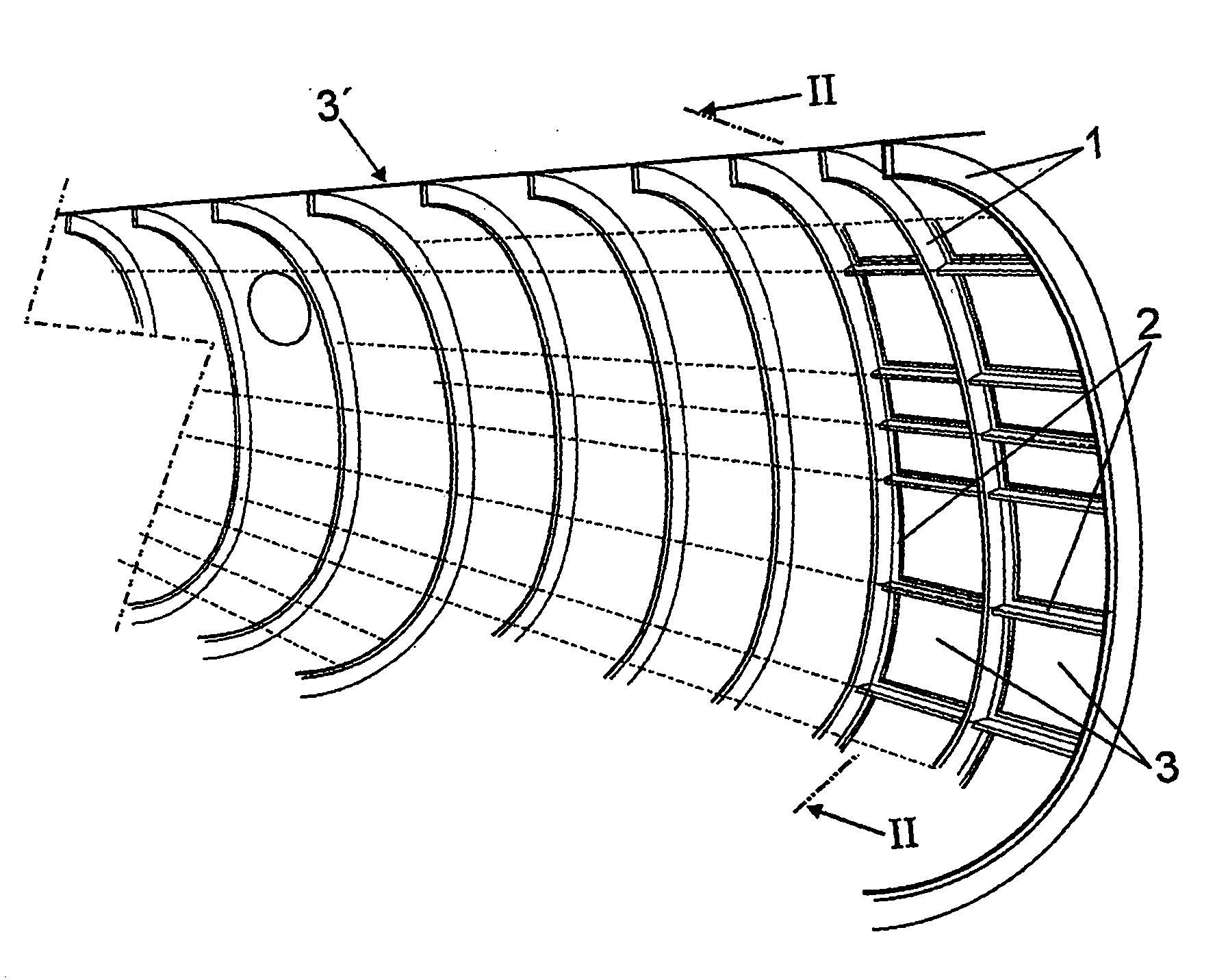
[0046] figure 1 shows an internal perspective view of an aircraft comprising a resistive structure comprising transverse ribs 1 and wing stringers 2, figure 2 The plate 3 forming the lining 3' is shown fastened thereto.

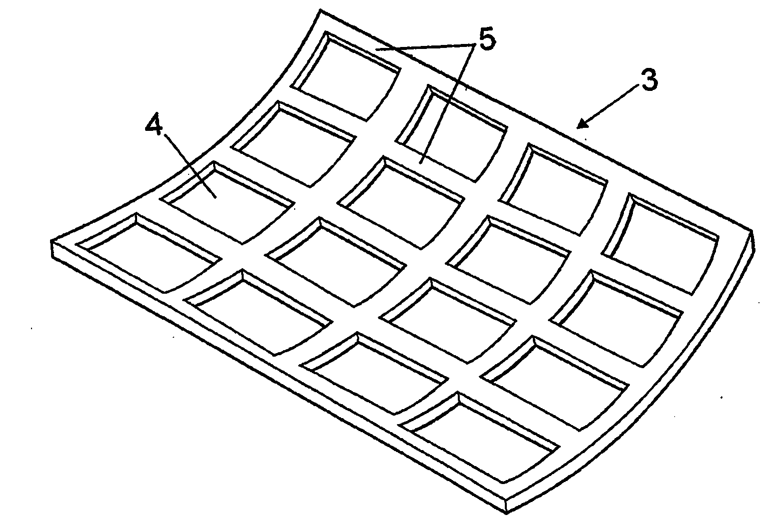
[0047] figure 2 Shown is an internal perspective view of one of these plates 3 having a recessed area 4 called a bay, which is delimited by a non-recessed strip 5 defining a Rib 1 and corresponding rib network for wing stringer 2 fastened thereto. The recess 4 makes it possible to reduce the weight of the lining panel 3 .

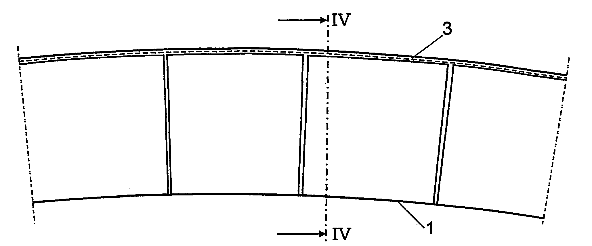
[0048] According to the present invention, in figure 1 The structural elements of the plate 3 on which the lining 3' is fastened, defined by the ribs 1 and the wing stringers 2, and the lining plate 3 comprise joint means consisting of a male dovetail formation 6 and a female The dovetail configuration 7 is defined, which can be obtained from image 3 and Figure 4 observed in. The male formations 6 will preferably form a pa...


PUM


Abstract

The invention relates to a coupling system for use between cladding and structural elements supporting same, said cladding comprising thin sheets (3) of alloys or composite materials. The facing surfaces of the sheets (3) and the structural elements (1 and 2) bear means for coupling said sheets and structural elements, which means are formed by male (6) and female (7) tongue-and-groove configurations provided along the length of at least part of the contact areas between the sheets and the structural elements.

Description

technical field [0001] The present invention relates to a joint system between a lining and a structural element supporting the lining, which can be applied in particular to the joints between the lining of an aircraft and a resistant structural element, especially in the field of aviation and in general Can be applied in areas where the liner consists of thin plates made of specific alloys or composites, and cleanup, friction minimization and non-perforation of the outer surface - due to which defects - are required basic characteristic. Background technique [0002] When analyzing the types of joints commonly used in the metallurgical industry at present, these joints can be divided into "rivet" joints (including here any joints that provide different parts with a stress transfer function between the parts to be joined) and welded joints . In certain fields of industry, such as the shipbuilding field, the motor vehicle field, the good results produced by welded joints ar...

Claims


Application Information

Patent Timeline
Patent Type & Authority Applications(China)
IPC IPC(8): B64C1/12B64C3/26F16B5/07
CPCB64C1/12F16B5/07B64C3/26F16B5/0052
Inventor 乔斯·安东尼奥·埃斯坦卡诺埃尔西利亚
Owner FORPLAN METALES
Learn More