Robot structure

A technology of robots and deceleration mechanisms, applied in manipulators, manufacturing tools, joints, etc., can solve problems such as reduced bearing capacity, hidden safety hazards, and asymmetric forces

Inactive Publication Date: 2011-05-11
HONG FU JIN PRECISION IND (SHENZHEN) CO LTD +1
View PDF8 Cites 9 Cited by
  • Summary
  • Abstract
  • Description
  • Claims
  • Application Information

AI Technical Summary

Problems solved by technology

Because both ends of the third wrist unit along the axial direction are in a suspended state, only one side in the circumferential direction is supported, resul...

Method used


Image

  • Robot structure
  • Robot structure
  • Robot structure

Examples


Embodiment Construction

[0013] The robot structure of the present invention will be further described in detail below in conjunction with the drawings and specific embodiments.

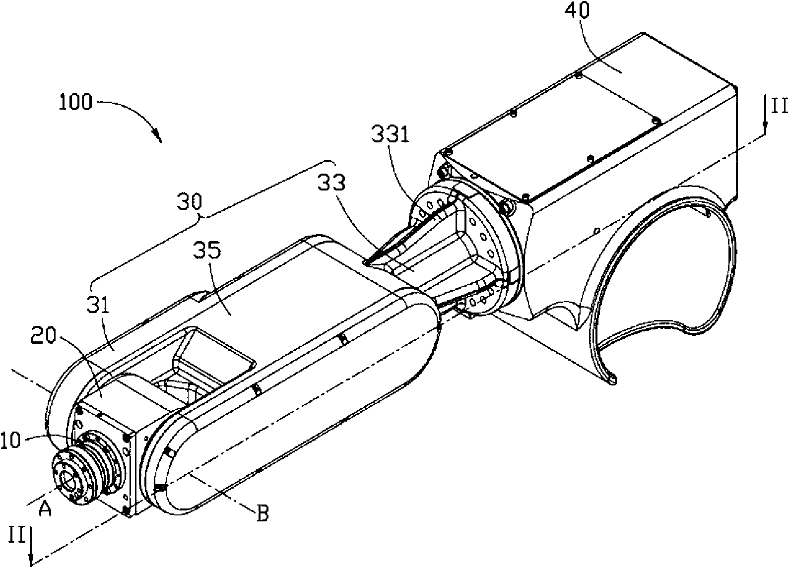
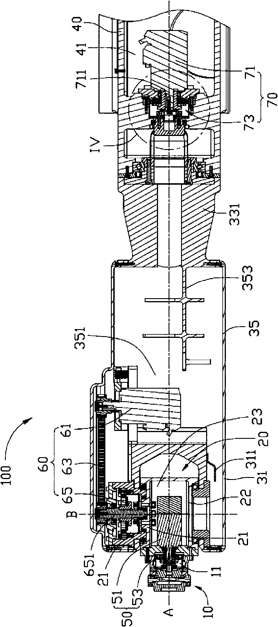
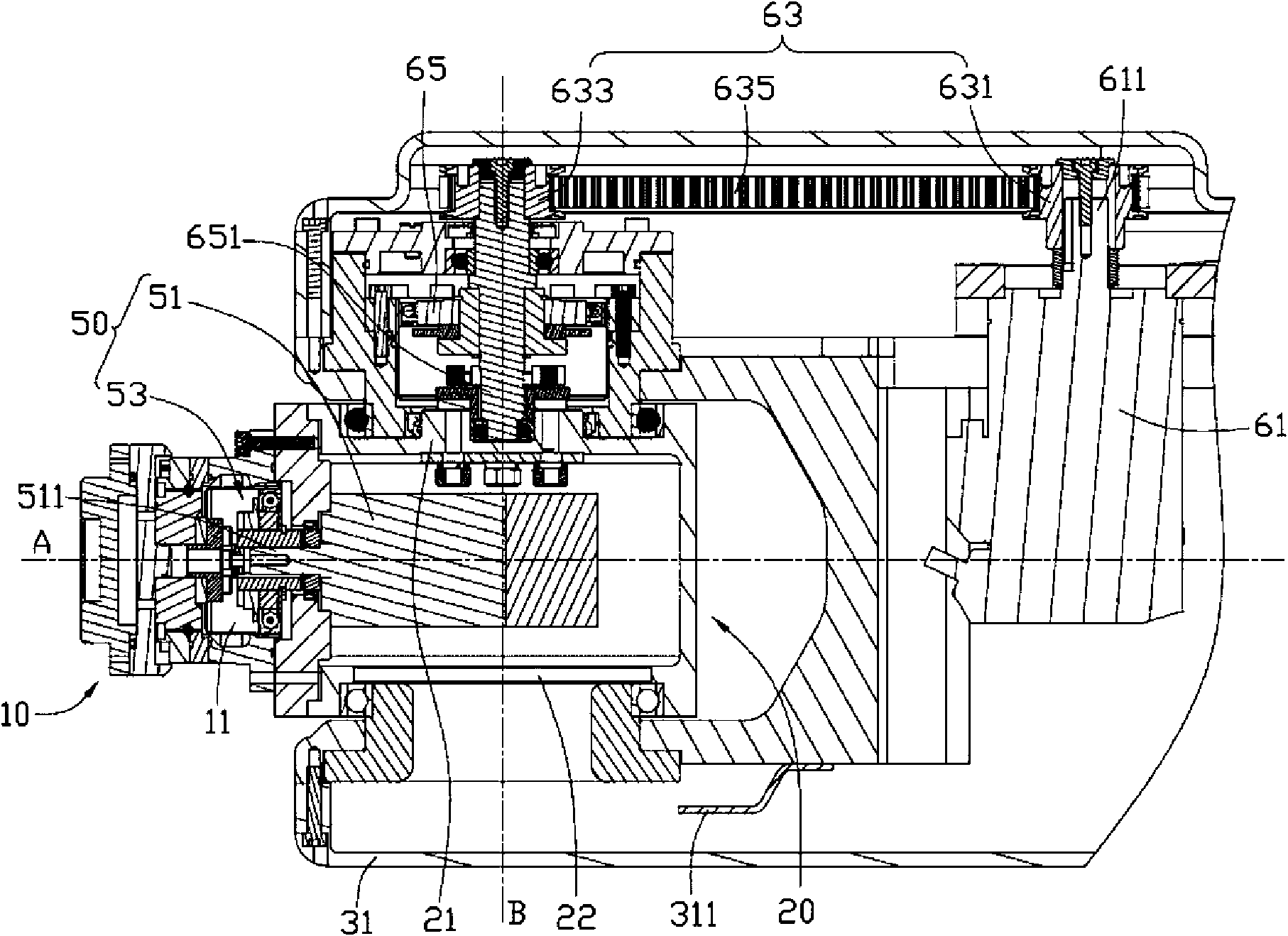
[0014] see figure 1 and figure 2 , the robot structure 100 includes a first shaft assembly 10 , a second shaft assembly 20 , a third shaft assembly 30 , and a fourth shaft assembly 40 that are pivotally connected to each other and relatively rotatable. The first wrist unit 50 at the junction, the second wrist unit 60 at the pivot joint between the second shaft assembly 20 and the third shaft assembly 30 , and the third wrist unit located at the pivot joint between the third shaft assembly 30 and the fourth shaft assembly 40 Unit 70.

[0015] Please also see image 3 , the first shaft assembly 10 is located at the extreme end of the robot structure 100, that is, it has a free end that is not connected with other parts, and the first shaft assembly 10 includes a plurality of matching elements, and one end of the first shaf...


PUM


Abstract

The invention discloses a robot structure, comprising a first shaft subassembly, a second shaft subassembly and a third shaft subassembly which are mutually pivoted and rotatable relatively, a first wrist unit at a pivoting part between the first shaft subassembly and the second shaft subassembly, and a second wrist unit at a pivoting part between the second shaft subassembly and the third shaft subassembly, wherein the first wrist unit comprises a first driving piece for driving the first wrist unit, the second wrist unit comprises a second driving piece for driving the second wrist unit, and the second wrist unit further comprises a transmission mechanism for transferring the power of the second driving piece to the second shaft subassembly, the first driving piece and the second driving piece are located at same side of the transmission mechanism, two ends of the second shaft subassembly are both pivoted with the third shaft subassembly, the first driving piece is arranged in the second shaft subassembly, the second driving piece is located in the third shaft subassembly, and the first driving piece and the second driving piece are arranged in a mutually approaching direction. The robot structure has the characteristics of small and smart structure and high carrying capacity.

Description

technical field [0001] The invention relates to a robot structure, in particular to a robot wrist structure. Background technique [0002] An industrial robot often includes a plurality of wrist units pivotally connected to each other, and performs different actions through the relative movement of the plurality of wrist units. The pivoting action at each wrist unit is usually realized by a reducer and a drive motor. [0003] The motion accuracy, carrying capacity, and motion stability of the wrist unit of the robot are all affected by the mutual positional relationship and actuation relationship between the components at the wrist unit. In order to arrange multiple robots in a limited space to achieve higher production efficiency, more and more robots need to be miniaturized. [0004] A robot wrist structure, which includes three axes: the first axis, the second axis and the third axis. Each axis is pivotally connected through the first and second wrist units in turn, and...

Claims


Application Information

Patent Timeline
IPC IPC(8): B25J17/00
CPCB25J17/0283
Inventor 龙波
Owner HONG FU JIN PRECISION IND (SHENZHEN) CO LTD
Why Eureka
Try Eureka