Waste gas protection system for thermal treatment furnace and control method

A protection system, heat treatment furnace technology, applied in the maintenance of heating chamber, furnace, furnace components, etc., can solve the problems of high nitrogen consumption, high manufacturing and use costs, large power consumption, etc., to achieve stable atmosphere and reduce air entry Effects in the furnace

Active Publication Date: 2011-05-11
HANGZHOU JINZHOU TECH CO INC
View PDF3 Cites 2 Cited by
  • Summary
  • Abstract
  • Description
  • Claims
  • Application Information

AI Technical Summary

Problems solved by technology

The disadvantages of its structure are: the nitrogen consumption of the vacuum chamber is relatively large, the power consumption is relatively large during use, and the manufacturing and use costs are relatively high

Method used


Image

  • Waste gas protection system for thermal treatment furnace and control method
  • Waste gas protection system for thermal treatment furnace and control method
  • Waste gas protection system for thermal treatment furnace and control method

Examples


Embodiment Construction

[0016] Below in conjunction with accompanying drawing and embodiment the present invention will be further described:

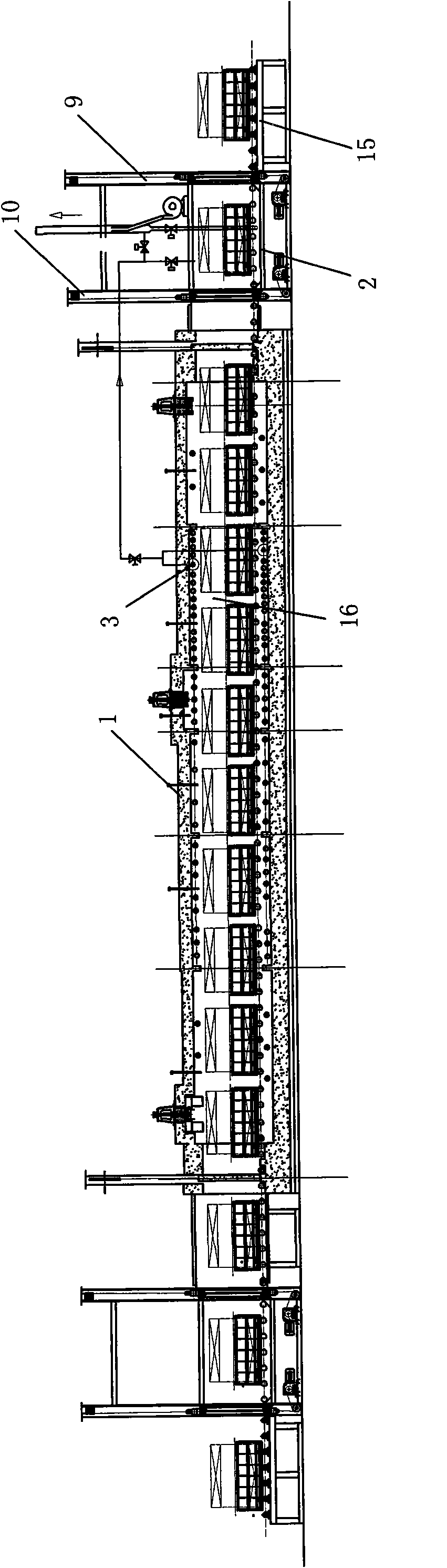
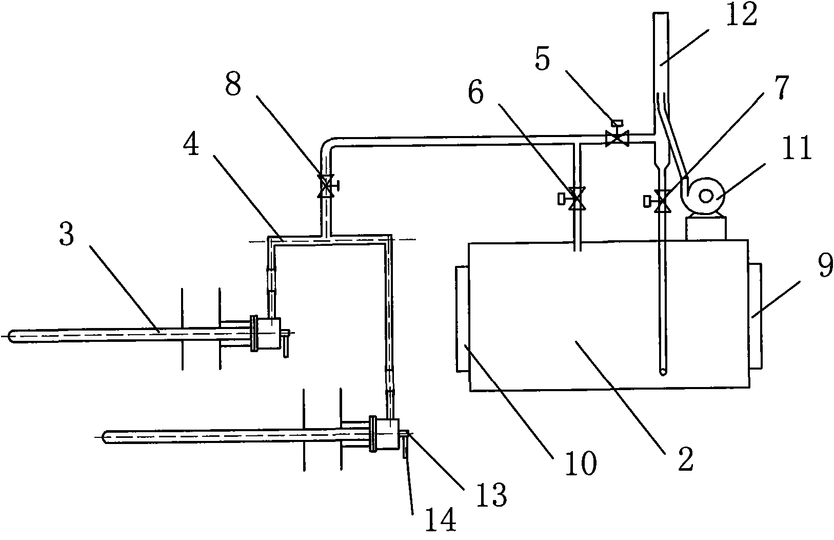
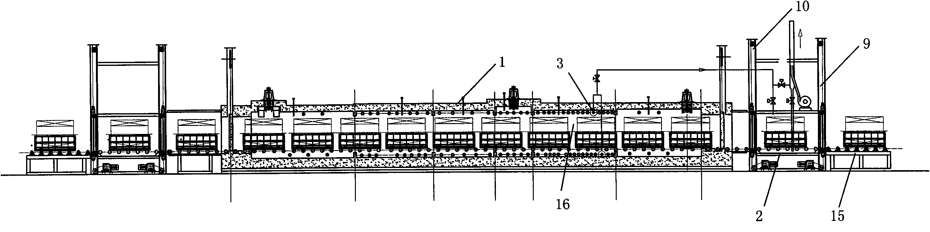
[0017] Such as figure 1 and figure 2 As shown, this exhaust gas protection system for a heat treatment furnace includes a furnace body 1 and a feed platform 15, an air replacement chamber 2 is arranged between the inlet of the furnace body 1 and the feed platform 15, and the air replacement chamber 2 and the inlet A No. 1 door 9 is provided between the material table 15, and a No. 2 door 10 is provided between the air replacement chamber 2 and the entrance of the body of furnace 1; the gas radiant pipe 3 in the heating chamber 16 part of the body of furnace 1 passes through the exhaust pipe 4 and The input ends of the fourth valve 8 are connected. The gas radiant pipe 3 includes a gas inlet 13 and an air inlet 14. This embodiment is divided into two groups, one group is arranged above the inner wall of the furnace body 1, and the other group is arranged on ...


PUM


Abstract

The invention relates to a waste gas protection system for a thermal treatment furnace and a control method. The system comprises a furnace body and a feeding table, an air displacement chamber is formed between the inlet of the furnace body and the feeding table, a No.1 door is arranged between the air displacement chamber and the feeding table, and a No.2 door is arranged between the air displacement chamber and the inlet of the furnace body; a fuel gas radiation pipe in the furnace body is connected with the input end of a fourth valve through an exhaust pipe, one path of the output end of the fourth valve is communicated with a burner waste gas exhaust pipe through a first valve, and the other path of the output end of the fourth valve is communicated with the cavity of the air displacement chamber through a second valve; and the burner waste gas exhaust pipe is communicated with the cavity of the air displacement chamber through a third valve, the system is provided with a blower, and the output port of the blower is arranged in the burner waste gas exhaust pipe. The system has the advantages that: a vacuum chamber is replaced by using the air displacement chamber, and the air in the air displacement chamber is displaced by using CO2 serving as a main component of the waste gas, so the air entering the furnace is reduced, and stability of furnace atmosphere is realized.

Description

technical field [0001] The invention relates to the field of heat treatment furnaces, in particular to an exhaust gas protection system and control method for heat treatment furnaces. Background technique [0002] In the protective atmosphere heat treatment equipment, high-purity nitrogen is used as the protective gas, and the heating furnace has good sealing performance. In order to ensure the purity of the protective atmosphere in the furnace and the stability of the furnace pressure, a vacuum air lock chamber is set at the connection between the inlet of the feed furnace and the outlet of the furnace and the furnace body as a transition, so that the feed and discharge are in the vacuum chamber. After stopping, pre-vacuumizing and filling with nitrogen, the annealed parts can be put into or out of the furnace. The disadvantages of its structure are: the nitrogen consumption of the vacuum chamber is relatively large, the power consumption is relatively large during use, an...

Claims


Application Information

Patent Timeline
Patent Type & Authority Applications(China)
IPC IPC(8): C21D1/74C21D1/76F27D7/06
Inventor 韩志根
Owner HANGZHOU JINZHOU TECH CO INC
Why Eureka
Try Eureka