Floor slab buckle connection structure

A technology for connecting structures and floors, which is applied in the field of building decoration materials, can solve the problems of increased floor manufacturing costs, floor damage and scrapping, and additional floors, and achieves the effect of low manufacturing costs

Inactive Publication Date: 2011-05-11
李增清
View PDF1 Cites 2 Cited by
  • Summary
  • Abstract
  • Description
  • Claims
  • Application Information

AI Technical Summary

Problems solved by technology

The above-mentioned technical solution directly processes the connecting structure on the side of the floor, which is difficult to process on the one hand, and can easily cause damage to the floor and scrap it, especially when the floor is made of w...

Method used


Image

  • Floor slab buckle connection structure
  • Floor slab buckle connection structure
  • Floor slab buckle connection structure

Examples


Embodiment 1

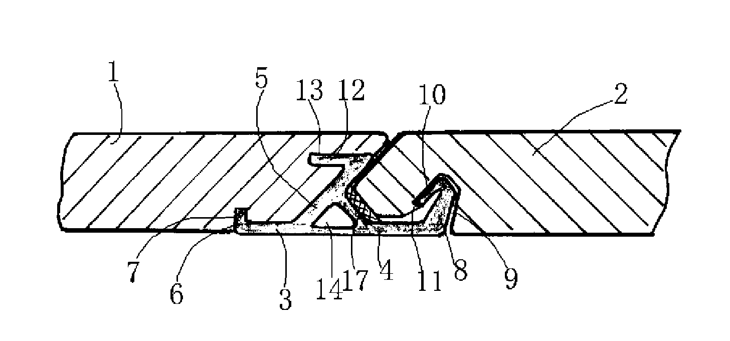
[0020] Embodiment 1: as figure 1 As shown, it includes the adjacent first floor 1 and the second floor 2, and the first floor 1 and the second floor 2 are connected to each other through the connecting piece 3 processed by the profile, and the connecting piece 3 includes a transverse part 4 and a transverse part 4 The upper convex part 5 integrally formed on the top, the bottom surface of the horizontal part 4 is flush with the bottom surface of the first floor and the bottom surface of the second floor, the connecting part 3 is bonded and fixed to the first floor 1, and the horizontal part 4 is connected to the first floor The corresponding end forms a lower first buckle portion 6 that is upturned, and a lower first buckle groove 7 corresponding to the lower first buckle portion 6 is formed on the bottom surface of the first floor, and the lower first buckle portion 6 Extending vertically upwards; the end of the horizontal part 4 corresponding to the second floor 2 forms a lo...

Embodiment 2

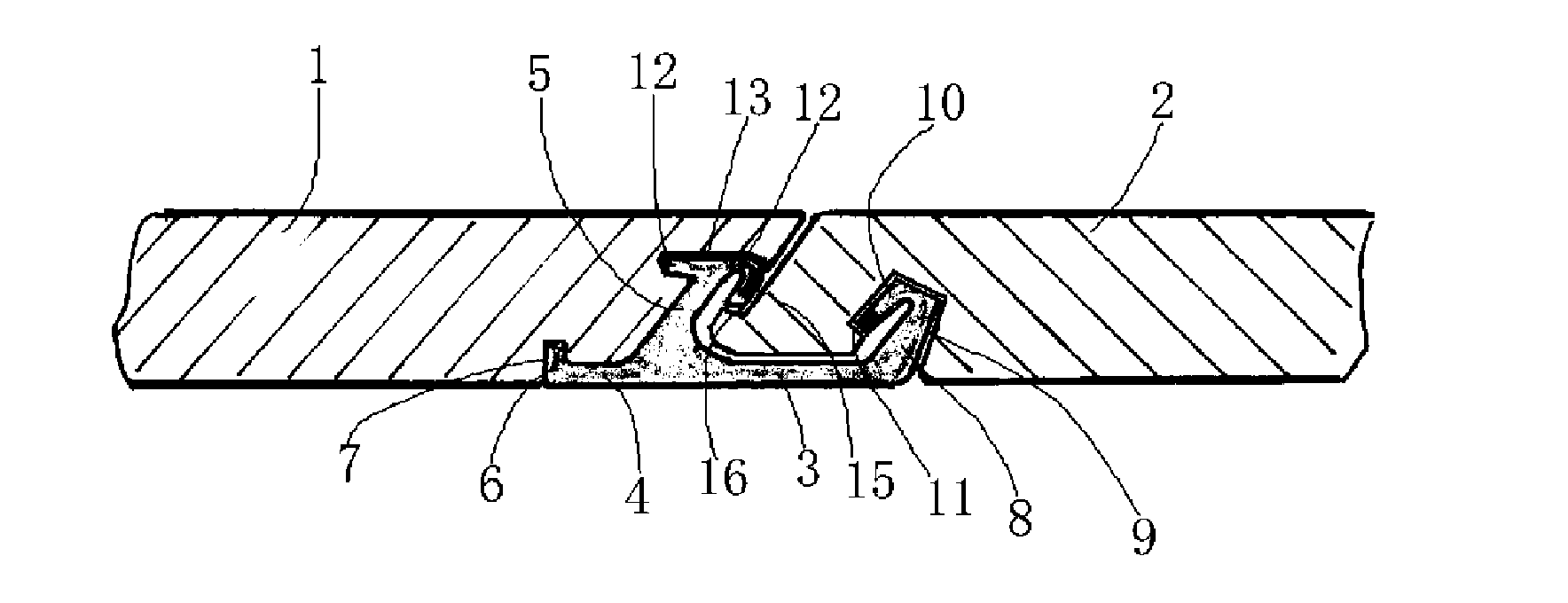
[0021] Embodiment 2: as figure 2As shown, it includes the adjacent first floor 1 and the second floor 2, and the first floor 1 and the second floor 2 are connected to each other through the connecting piece 3 processed by the profile, and the connecting piece 3 includes a transverse part 4 and a transverse part 4 The upper convex part 5 integrally formed on the top, the bottom surface of the horizontal part 4 is flush with the bottom surface of the first floor 1 and the bottom surface of the second floor 2, the connecting part 3 is bonded and fixed with the first floor 1, and the horizontal part 4 is connected to the second floor. One end corresponding to the floor forms a lower first buckle portion 6 that is upturned, and a lower first buckle groove 7 corresponding to the lower first buckle portion 6 is formed on the bottom surface of the first floor, and the lower first buckle The part 6 extends vertically upward; the end of the horizontal part 4 corresponding to the second...

Embodiment 3

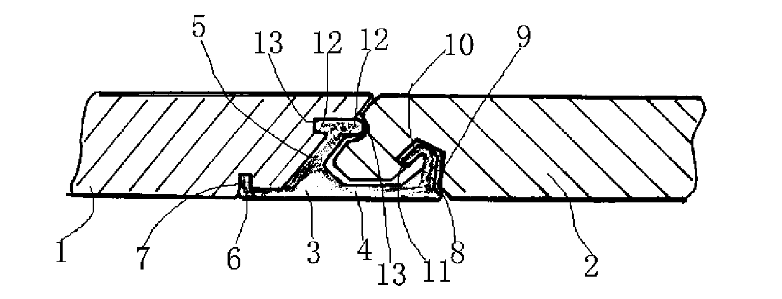
[0022] Embodiment 3: as image 3 As shown, it includes the adjacent first floor 1 and the second floor 2, and the first floor 1 and the second floor 2 are connected to each other through the connecting piece 3 processed by the profile, and the connecting piece 3 includes a transverse part 4 and a transverse part 4 The upper convex part 5 integrally formed on the top, the bottom surface of the horizontal part 4 is flush with the bottom surface of the first floor 1 and the bottom surface of the second floor 2, the connecting part 3 is bonded and fixed with the first floor 1, and the horizontal part 4 is connected to the second floor. One end corresponding to the floor forms a lower first buckle portion 6 that is upturned, and a lower first buckle groove 7 corresponding to the lower first buckle portion 6 is formed on the bottom surface of the first floor, and the lower first buckle The part 6 extends vertically upward; the end of the horizontal part 4 corresponding to the second...


PUM


Abstract

The invention relates to a floor slab buckle connection structure, which belongs to the technical field of building decoration materials. The floor slab buckle connection structure comprises a first floor slab and a second floor slab which are adjacent to each other, wherein the first floor slab and the second floor slab are connected with each other through a connecting piece; the connecting piece comprises a transverse part and an upper convex part which is integrally formed on the transverse part; the bottom surface of the transverse part is flush with the bottom surface of the first floor slab and the bottom surface of the second floor slab; the end of the transverse part corresponding to the first floor slab is provided with first upswept lower buckling part; the bottom surface of the first floor slab is provided with a first lower buckling groove corresponding to a first lower buckling part; the end of the transverse part corresponding to the second floor slab is provided with a second upswept lower buckling part; the bottom surface of the second floor slab is provided with a second lower buckling groove corresponding to a second lower buckling part; a transverse buckling part facing the first floor slab or the second floor slab is formed on at least one side of the upper convex part; a side edge of the first floor slab or a side edge of the second floor slab is provided with a transverse buckling groove which is matched with the transverse buckling part; and the connecting piece is machined by a section. The floor slabs and the connecting piece are separately manufactured, so the floor slabs are prevented from being damaged or scrapped, and the floor slab buckle connection structure has lower manufacturing cost.

Description

technical field [0001] The invention relates to a floor buckle connection structure, which belongs to the technical field of building decoration materials. Background technique [0002] In the prior art, the connection between two adjacent floors is usually realized by directly processing the connection structure on the side of the floor. For example, a Chinese patent discloses a self-locking connection floor (Patent No.: CN02158232.7) , including a floor body, a first tongue protrudes from one side of the floor body to the outside, and a first slot is recessed from the other side of the floor body to the inside, and the first tongue There is a second slot under the bottom of the second slot, and the upper or lower wall of the second slot is provided with a locking groove that is recessed along the direction perpendicular to the horizontal plane, and the bottom of the first slot is provided with a second tongue , the upper or lower surface of the second tongue is provided w...

Claims


Application Information

Patent Timeline
IPC IPC(8): E04F15/02
Inventor 李增清
Owner 李增清
Why Eureka
Try Eureka