Circulating ventilation fan system

A fan system and fan technology, applied in the field of ventilation systems, can solve the problems of time-consuming and labor-intensive installation, increased production costs, and increased heat sources, and achieve the effects of easy installation, easy production, and fewer heat sources

Inactive Publication Date: 2011-05-11
胡剑峰
View PDF0 Cites 5 Cited by
  • Summary
  • Abstract
  • Description
  • Claims
  • Application Information

AI Technical Summary

Problems solved by technology

At present, the indoor circulation and ventilation systems used in many aging houses need to rely on two sets of fans, namely the circulation fan and the ventilation fan, which not only increase the

Method used


Image

  • Circulating ventilation fan system
  • Circulating ventilation fan system

Examples


Embodiment Construction

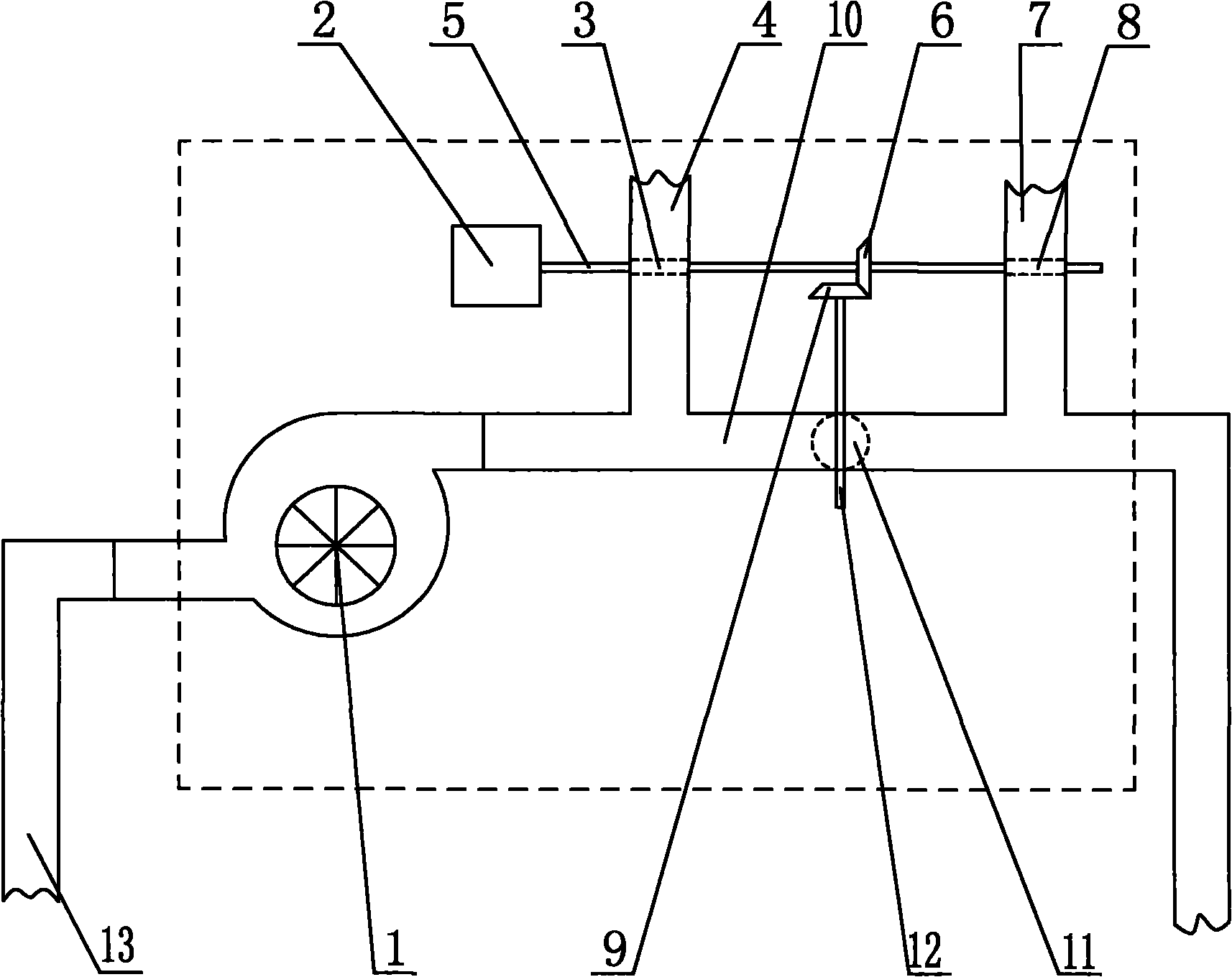
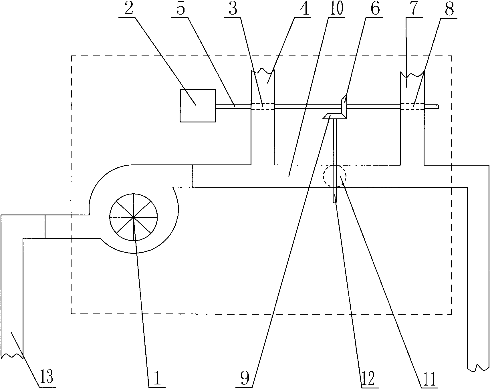
[0023] like figure 1 A circulating ventilation fan system is shown, including a fan 1, a motor 2, a drive shaft 5 connected coaxially with the power output shaft of the motor 2 and used to drive the valve 1 3 and the valve 2 8, and a drive shaft 5 for driving the valve 3 The transmission shaft 12 of 11, the air inlet of the fan 1 is connected with the indoor pipeline 13, the outlet of the fan 1 is connected with the circulation pipeline 10, and the side wall of the circulation pipeline 10 is provided with an outdoor pipeline 4 connected with it and outdoor pipeline two 7, the transmission shaft one 5 is arranged on the outdoor pipeline one 4 and the outdoor pipeline two 7, the transmission shaft two 12 is arranged on the circulation pipeline 10, and the transmission shaft one 5 is located on the outdoor pipeline one 4 and the outdoor pipeline two The part between the outdoor pipeline two 7 is equipped with a shaft sleeve helical gear one 6, and the end of the transmission shaf...


PUM


Abstract

The invention discloses a circulating ventilation fan system, which comprises a fan, a motor, a transmission shaft I and a transmission shaft II, wherein the air inlet of the fan is communicated with an indoor pipeline, the outlet of the fan is communicated with a circulating pipeline, and the side wall of the circulating pipeline is provided with an outdoor pipeline I and an outdoor pipeline II communicated with the circulating pipeline; the transmission shaft I is arranged on the outdoor pipeline I and the outdoor pipeline II; the transmission shaft II is arranged on the circulating pipeline; the part, positioned between the outdoor pipeline I and the outdoor pipeline II, of the transmission shaft I is provided with a shaft sleeve bevel gear I; the end of the transmission shaft II is matched with the shaft sleeve bevel gear I and provided with a shaft sleeve bevel gear II; and a valve I, a valve II and a valve III are arranged in the outdoor pipeline I, the outdoor pipeline II and the circulating pipeline. The circulating ventilation fan system has the characteristics of simple structure, a few heating sources, reasonable design, installation convenience, high work efficiency, low production cost and convenience for popularization and use.

Description

technical field [0001] The invention discloses a ventilation system, in particular to a circulating ventilation fan system which can provide indoor air circulation function for an aging room and realize air exchange inside and outside the room. Background technique [0002] The aging room, also known as the burn-in room, is a simulation room for high-performance electronic products (such as computer machines, monitors, terminals, automotive electronics, power supplies, motherboards, monitors, and switching chargers, etc.). A high-temperature, harsh test environment equipment is an important experimental equipment to improve product stability and reliability. This equipment has been widely used in power electronics, computers, communications, biopharmaceuticals and other fields. [0003] The indoor circulation and ventilation function of the aging room is an important link to ensure the smooth progress of production. At present, the indoor circulation and ventilation systems...

Claims


Application Information

Patent Timeline
IPC IPC(8): F24F7/06F24F13/02
Inventor 胡剑峰
Owner 胡剑峰
Why Eureka
Try Eureka