
Square-wave generator and system and method for calibratig resistance voltage divider

A square wave generator and calibration system technology, which is applied in the direction of instruments, measuring electrical variables, measuring devices, etc., can solve the problem of not meeting the requirements of the water resistance voltage divider, the calibration system of the water resistance voltage divider is not standardized, and the connection pair calibration Issues such as large impact on the results

Inactive Publication Date: 2011-05-11
XI AN JIAOTONG UNIV +2
View PDF2 Cites 7 Cited by
  • Summary
  • Abstract
  • Description
  • Claims
  • Application Information

AI Technical Summary

Problems solved by technology

[0003] However, the rising edge of the existing square wave source output square wave is mostly slow, which cannot meet the requirements of calibrating the water resistance divider with nanosecond response
[0004] In addition, the calibration system of the water resistor divider is not standardized, and the connection has a great influence on the calibration results
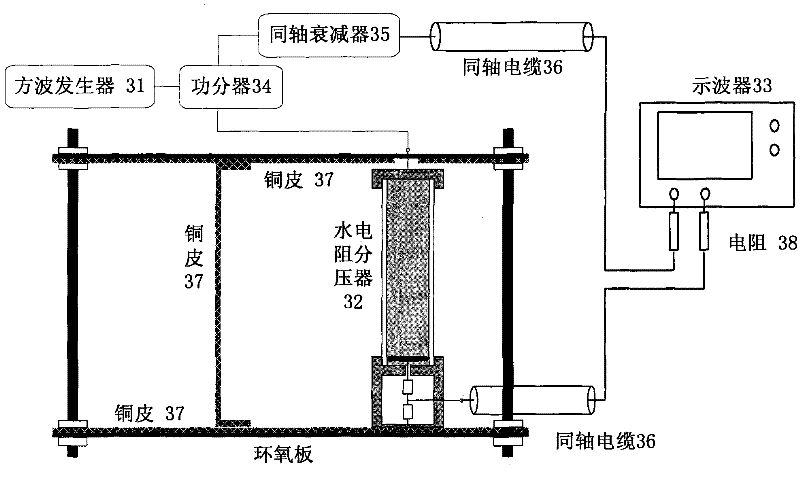
In practical applications, since the response time of the water resistance divider is closely related to its capacitance to ground, when the capacitance to ground becomes larger, the response of the voltage divider will slow down; due to the relatively large size of the water resistance divider, if the wiring As the area enclosed by the loop becomes larger, it will be difficult to measure the square wave signal with a faster rising edge due to the increase of the loop inductance.

Method used


Image

  • Square-wave generator and system and method for calibratig resistance voltage divider
  • Square-wave generator and system and method for calibratig resistance voltage divider
  • Square-wave generator and system and method for calibratig resistance voltage divider

Examples


Embodiment Construction

[0021] The present invention will be described more fully hereinafter with reference to the accompanying drawings, in which exemplary embodiments of the invention are illustrated.

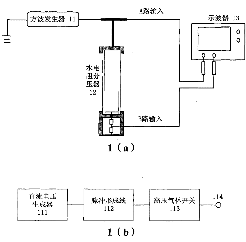
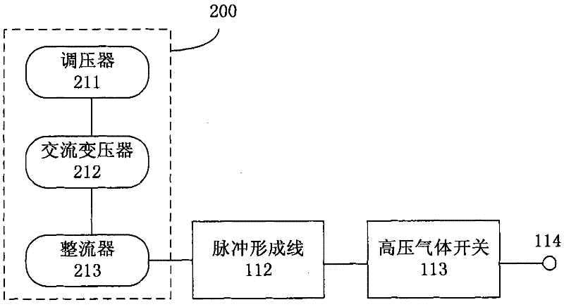
[0022] figure 1 A schematic diagram showing an embodiment of the water resistance divider calibration system of the present invention. in figure 1 (a) shows the schematic diagram of this embodiment calibration system, figure 1 (b) shows a block diagram of the square wave generator of this embodiment. exist figure 1 In (a), the calibration system includes a square wave generator 11 , a water resistor divider 12 and an oscilloscope 13 . Square wave generator 11 produces square wave signal; Square wave signal is divided into two-way signal, is transmitted to water resistance voltage divider 12 and oscilloscope 13 respectively; The water resistor divider 12 is calibrated. exist figure 1 In (b), the square wave generator 11 includes a DC voltage generator 111 , a pulse forming line 112 , a high-p...


PUM


Abstract

The invention discloses a system and a method for calibrating a water resistance voltage divider and a square-wave generator. The system comprises a square-wave generator and a water resistance voltage divider connected with the square-wave generator which is used for providing a square-wave signal and comprises a DC (Direct Current) voltage generator, a pulse forming line, a high-voltage gas switch and an output end in connection, wherein the DC voltage generator is used for outputting a DC voltage for charging the pulse forming line; and when the spark gap of the high-voltage gas switch is broken down by the pulse forming line, the output end outputs a square-wave signal. The water resistance voltage divider is calibrated by adopting the square-wave generator, and the generated square-wave signal rising edge has higher speed. A coaxial cable is adopted to connect a square-wave source and a specified-measuring calibration system as well as the measured water resistance voltage divider, and a broadband coaxial attenuator can decrease the amplitude of an original waveform and have less distortion so that the water resistance voltage divider can be accurately calibrated finally.

Description

technical field [0001] The invention relates to the technical field of high-power pulses, in particular to a calibration system and method for an electric square wave generator and a resistor divider. Background technique [0002] In the field of high-power pulse technology, how to accurately measure the high-voltage fast frontier pulse signal is a subject of continuous research. The use of water resistance voltage divider is a widely used measurement method. Before the water resistance voltage divider is used, the water resistance voltage divider needs to be calibrated. At present, the more common calibration method is to use a square wave source and use the comparison method for calibration. A square wave generator can be used as a square wave source. A square wave generator usually refers to a pulse voltage source that can generate a pulse with a certain rise time, a certain pulse width, and a rectangular waveform. [0003] However, most of the rising edges of the outp...

Claims


Application Information

Patent Timeline
IPC IPC(8): G01R35/02
Inventor 丁卫东马宾李峰张乔根李志兵王浩
Owner XI AN JIAOTONG UNIV
Learn More