
Voltage regulator with gate resistor for improved efficiency

A technology of voltage regulator and grid resistance, which is applied in high-efficiency power electronic conversion, output power conversion device, conversion equipment without intermediate conversion to AC, etc., can solve the problems of expensive and inefficient traditional methods.

Inactive Publication Date: 2011-05-11
NXP BV
View PDF3 Cites 4 Cited by
  • Summary
  • Abstract
  • Description
  • Claims
  • Application Information

AI Technical Summary

Problems solved by technology

However, these traditional methods are relatively expensive and / or inefficient

Method used


Image

  • Voltage regulator with gate resistor for improved efficiency
  • Voltage regulator with gate resistor for improved efficiency
  • Voltage regulator with gate resistor for improved efficiency

Examples


Embodiment Construction

[0013] It should be understood that the components of the embodiments generally described herein and illustrated in the drawings may be arranged and designed in many different configurations. Accordingly, the following more detailed description of various embodiments as presented in the accompanying drawings is not intended to limit the scope of the present disclosure, but merely represents different embodiments. While the various aspects of the embodiments are shown in the drawings, the drawings are not necessarily drawn to scale unless otherwise indicated.

[0014] The present invention may be embodied in other specific forms without departing from the spirit and essential characteristics of the invention. The described embodiments are to be considered in all respects as illustrative rather than restrictive. It is therefore intended that the scope of the present invention be indicated by the appended claims rather than by the detailed description herein. All changes within...


PUM


Abstract

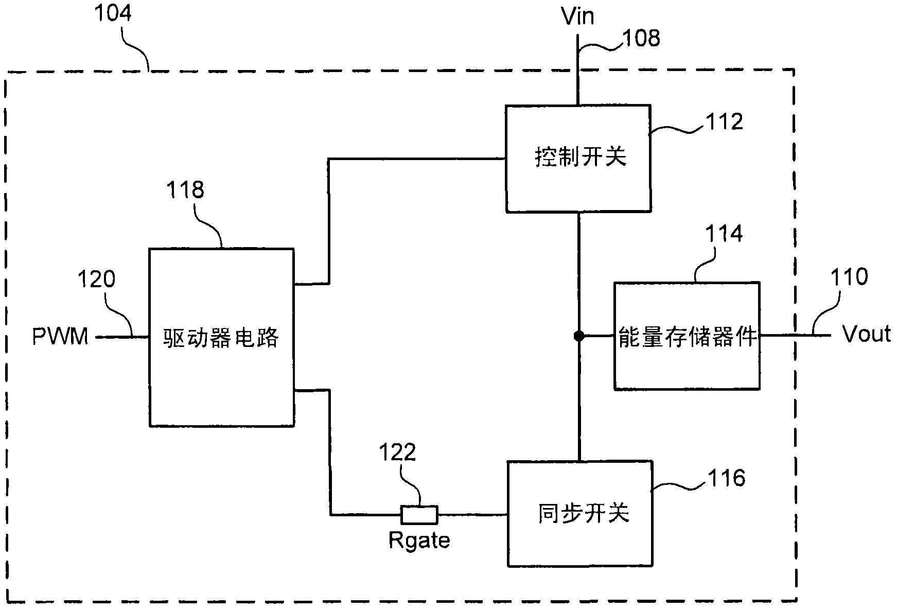
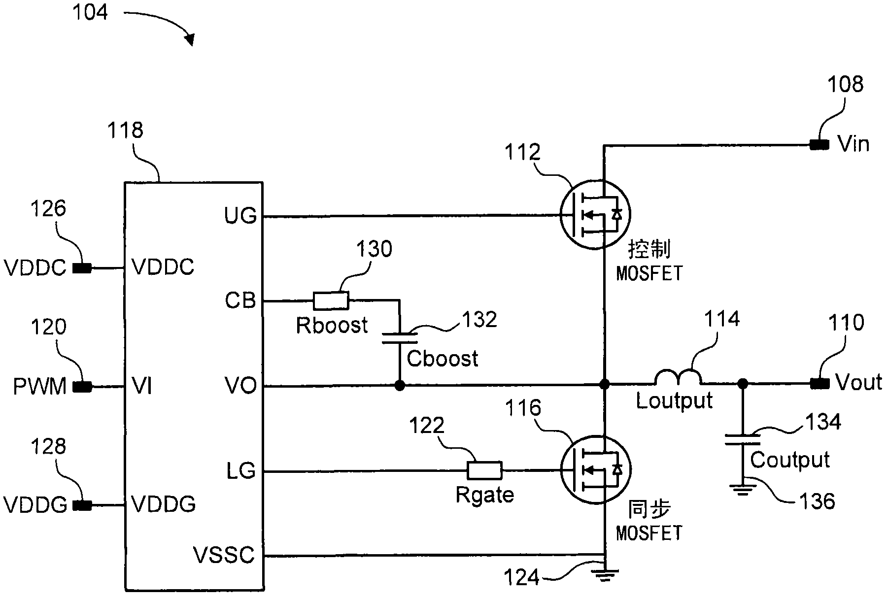
A voltage regulator includes an active control switch, an active sync switch, a driver circuit, and a gate resistor. The active control switch is coupled between an input voltage line and an input of an energy storage device. The active sync switch is coupled to the input of the energy storage device. The driver circuit is coupled to the control and sync switches to alternately drive each of the control and sync switches into a conducting state to produce a regulated voltage at an output of the energy storage device. The gate resistor is coupled in series within a control path of the sync switch. The gate resistor has a resistance value that is tuned to reduce an anticipated dead time between a turn-off time of the sync switch and a turn-on time of the control switch.

Description

technical field [0001] The present invention relates to voltage regulators, and more particularly to voltage regulators with gate resistors for improved efficiency. Background technique [0002] Voltage regulators are used in electronic equipment to provide a regulated voltage to a load. Switch-mode voltage regulators use a pair of switches, such as control and synchronous MOSFET switches, to regulate the voltage output from the regulator. The switches are alternately turned on and off and output a regulated voltage from an energy storage device such as an inductor connected between the switches. [0003] Conventional switch-mode voltage regulators experience voltage spikes when the control MOSFET is turned on because the reverse recovery current of the body diode of the synchronous MOSFET allows excessive current flow when the synchronous MOSFET is turned off. Traditional methods of addressing these voltage spikes include: using a Schottky or fast recovery diode implement...

Claims


Application Information

Patent Timeline
IPC IPC(8): H02M3/07H02M1/14
CPCH02M3/1588Y02B70/10
Inventor 李东浩
Owner NXP BV
Learn More