Combination unit for multilevel heat exchange and gas liquid separation

A technology of gas-liquid separation and combined equipment, which is applied in heat exchange equipment, use of liquid separating agent, lighting and heating equipment, etc. It can solve the problems of increased gas pressure drop, low heat exchange efficiency, and small heat exchange area, and achieves Reduced flow resistance, reduced production energy consumption, and high heat transfer efficiency

Active Publication Date: 2011-05-18
ANHUI SHIHUA ENG & TECH
View PDF5 Cites 16 Cited by
  • Summary
  • Abstract
  • Description
  • Claims
  • Application Information

AI Technical Summary

Problems solved by technology

The equipment has the functions of cooling gas and gas-liquid separation, but there are certain limitations in use, first of all, the problem of equipment structure: because the droplets gathered by the high-efficiency foam-breaking mist catcher and the droplets condensed by the tube-and-tube air-water cooler rely on gravity Settling, which flows in the opposite direction to the rising gas, will cause liquid entrainment in the gas or increase in the pressure drop of the gas when the gas flow rate is high; the heat exchange area of ​​the two-tube air-water cooler depends on the number of tubes, The heat exchange area is small and the heat exchange efficiency is low. Once the heat exchange tube bundle is corroded and perforated, the whole equipment will be scrapped; thirdly, the effect of the equipment is only equivalent to: a first-level gas condenser + a first-level gas-liquid separator. When gas multi-stage cooling and gas-liquid separation, it still needs a combination of multiple equipment to solve

Method used


Image

  • Combination unit for multilevel heat exchange and gas liquid separation
  • Combination unit for multilevel heat exchange and gas liquid separation
  • Combination unit for multilevel heat exchange and gas liquid separation

Examples


Embodiment

[0027] Example: A stream of distillation gas is extracted from the side line of a distillation tower in a factory, and a "first-stage shell-and-tube condenser + a first-stage gas-liquid separator" is used to extract the first-stage condensate under the conditions of temperature T1 and pressure P1; Shell condenser + secondary gas-liquid separator" extracts the secondary condensate under the conditions of temperature T2 and pressure P2; adopts "three-stage shell-and-tube condenser + three-stage gas-liquid separator" to extract the secondary condensate under the conditions of temperature T3 and pressure P3 Under the extraction of tertiary condensate and non-condensable gas.

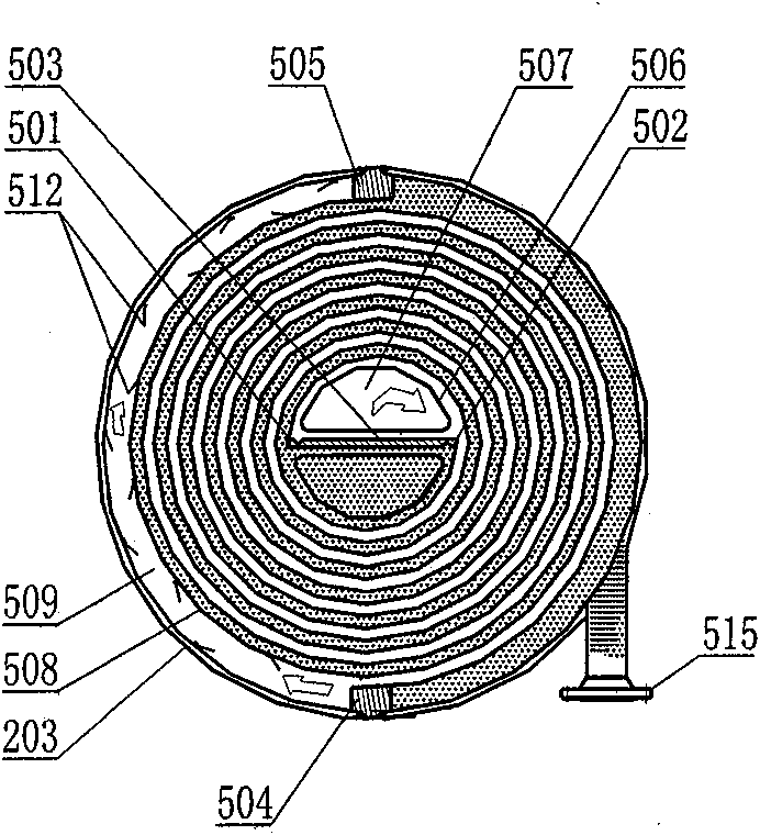
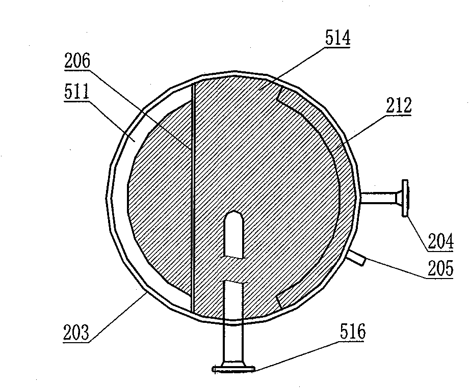
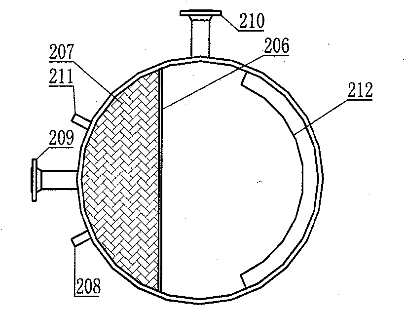
[0028] The preferred implementation mode adopted in the present invention: without changing the process flow and process conditions of the examples, the modular equipment with the functions of heat exchange, gas-liquid separation, and condensate collection are combined into a tower-shaped overall equipment to...


PUM


Abstract

The invention discloses a combination unit for carrying out segmented control on heat exchange temperature and pressure of a multi-component gas, gas liquid separation, and staged recover of condensate. The combination unit is tower-shaped equipment, and is divided into upper, middle and lower parts, wherein the three parts are connected by flanges. The gas flows in the tower from bottom to top; the lower part of the tower body is used for removing the entrained liquid of a gas which enters into the tower, and collecting the condensate generated by upper heat-exchange equipment; the middle part of the tower body is formed by multiple sections of modular equipment; a heat exchanger of the modular equipment at each section is a spiral-plate exchanger; the modular equipment at each section is used for automatically controlling the heat exchange temperature and pressure of a gas and gas liquid separation, and is used for collecting condensate produced by the modular equipment at the previous section; and the upper part of the tower body is used for primarily and automatically controlling the heat exchange temperature and pressure of a gas and gas liquid separation. The combination unit is characterized in that the section number of the modular equipment can be freely and flexibly selected so as to be combined with the upper part and the lower part of the lower into the whole equipment, thus meeting the production requirements for progressive heat exchange of the gas, gas liquid separation and staged recover of the condensate.

Description

technical field [0001] The invention relates to a device with functions of heat exchange and gas-liquid separation, in particular to a combined device for segmentally controlling the heat transfer temperature and pressure of multi-component gas, gas-liquid separation, and graded recovery of condensate. Background technique [0002] In the process of industrial production, the distillation gas produced contains multiple components, and the various components in the gas need to be separated during production. A process method that is often used is based on the saturated vapor pressure, The condensation point is different, the temperature and pressure of the gas heat exchange are controlled in sections, the gas-liquid separation is carried out, and the condensate is recovered in stages. At present, the production process commonly used in factories is: first-stage gas condenser + first-stage gas-liquid separator + second-stage gas condenser + second-stage gas-liquid separator + ...

Claims


Application Information

Patent Timeline
Patent Type & Authority Applications(China)
IPC IPC(8): B01D53/26B01D47/02F28D9/04F28F9/02F28F3/02
Inventor 陈群张志宏
Owner ANHUI SHIHUA ENG & TECH
Why Eureka
Try Eureka