
Trussed sludge circulation clarifying pool

A technology of clarifier tanks and truss trucks, applied in water/sludge/sewage treatment, water/sewage multi-stage treatment, settling tanks, etc., can solve problems such as high water source pressure requirements, complex pool structure, and large water head. Achieve enhanced mud-water separation effect, simple pool structure, and high-quality treated water

Active Publication Date: 2012-11-14
HEBEI AEROSPACE ENVIRONMENTAL ENG CO LTD
View PDF0 Cites 0 Cited by
  • Summary
  • Abstract
  • Description
  • Claims
  • Application Information

AI Technical Summary

Problems solved by technology

Among them, the sludge circulation clarifier mainly refers to the mechanical stirring clarification tank, which requires mechanical stirring equipment, the structure of the tank body is complicated, and the maintenance is troublesome; the sludge circulation clarification tank mainly refers to the hydraulic circulation clarification tank, without mechanical stirring equipment, and the structure is relatively Simple, but consumes a large head of water, and the pressure of the water source is high
The sludge suspension type clarifier also needs a set of vacuum equipment, the structure is relatively complicated, and the operation and management requirements are relatively high
[0003] Through the search, no public literature on the truss truck type sludge circulating clarifier has been found

Method used


Image

  • Trussed sludge circulation clarifying pool
  • Trussed sludge circulation clarifying pool
  • Trussed sludge circulation clarifying pool

Examples


Embodiment Construction

[0018] The present invention will be further described in detail below in conjunction with the accompanying drawings and through specific embodiments. The following embodiments are only descriptive, not restrictive, and cannot limit the protection scope of the present invention.

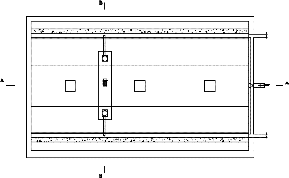
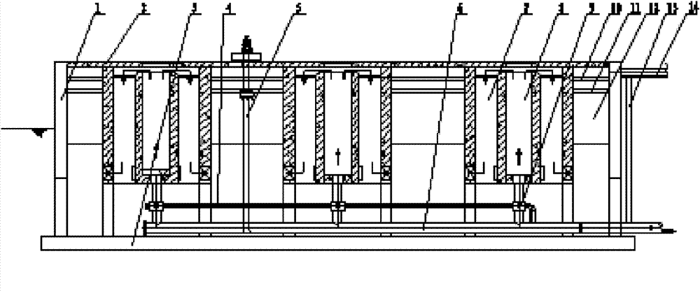
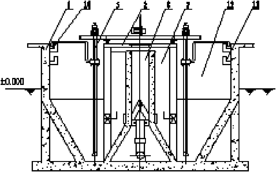
[0019] A truss-type sludge circulation clarifier, which is a cuboid or circular tank structure, including a tank wall 1, a tank bottom 3, a water inlet pipe 6, a multiphase mixer 9, a first coagulation reaction zone 8, a second Coagulation reaction zone 7, sedimentation zone 12, truss truck type sludge suction device 5, sludge return weir and channel 10, sludge return pipeline 13, outlet weir and channel 11, sludge discharge pipeline 14, etc., clarifier cover is equipped with cover plate 2 , a plurality of coagulation reaction zones are evenly distributed in the horizontal direction, and there are three coagulation reaction zones in this embodiment; Between the periphery of each coagulation reaction ...


PUM

PropertyMeasurementUnit
Reynolds numberaaaaaaaaaa

Abstract

The invention relates to a trussed sludge circulation clarifying pool. A plurality of coagulation reaction zones are uniformly arranged at the horizontal direction according to different quantities of water, each coagulation reaction zone comprises a first coagulation reaction zone and a second coagulation reaction zone with two sides arranged in a mirror image way, precipitation zones are arranged between the periphery of each coagulation reaction zone and the pool wall, the coagulation reaction zones and the precipitation zones all are connected in an integrated concrete pouring manner, a multi-phase mixer is arranged at the lower part of each coagulation reaction zone via a pipeline, a water inlet pipeline paved at the bottom of the pool is communicated with the multi-phase mixer, two trussed mud-sucking devices are symmetrically arranged in the clarifying pool and can travel on a track fixedly arranged on a cover plate of the clarifying pool, and mud-sucking pipes at the lower ends of the mud-sucking devices are arranged at the bottom of the pool. By virtue of the trussed mud-sucking devices, sludge circulation is realized, a reaction zone which integrates the functions of mixing, flocculation and precipitation is built in the clarifying pool, and the trussed mud-sucking devices can be directly applied to the sludge circulation clarifying pool and has the characteristics of high clarifying efficiency and excellent treated water quality.

Description

technical field [0001] The invention belongs to the field of sewage treatment process integration devices, in particular to a truss-car type sludge circulation clarifier. Background technique [0002] At present, the clarifiers used for water clarification and advanced sewage treatment in sewage treatment mainly include two forms, namely sludge suspension clarifiers and sludge circulation clarifiers. Among them, the sludge circulation clarifier mainly refers to the mechanical stirring clarification tank, which requires mechanical stirring equipment, the structure of the tank body is complicated, and the maintenance is troublesome; the sludge circulation clarification tank mainly refers to the hydraulic circulation clarification tank, without mechanical stirring equipment, and the structure is relatively It is simple, but consumes a large head of water, and the pressure of the water source is high. The sludge suspension type clarifier also needs a set of vacuum equipment, th...

Claims


Application Information

Patent Timeline
Patent Type & Authority Patents(China)
IPC IPC(8): B01D21/04C02F9/04
Inventor 滕朝华朱鹏程高用贵安惠欣林益峰张冬梁冠亮谭丽程恒
Owner HEBEI AEROSPACE ENVIRONMENTAL ENG CO LTD
Learn More