Rotary self-sealing well sealer
A technology of sealing device and self-sealing glue, which is applied in the directions of sealing/isolation, wellbore/well components, earthwork drilling and production, etc., and can solve the problems that self-sealing sealing devices cannot meet the rotary sealing function
- Summary
- Abstract
- Description
- Claims
- Application Information
AI Technical Summary
Problems solved by technology
Method used
Image

Examples
Embodiment 1
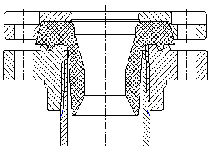
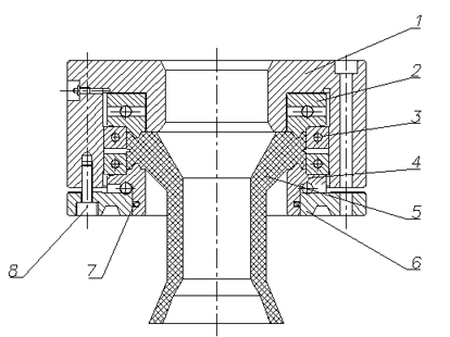
[0027] Such as figure 2 As shown in the structural diagram of the embodiment of the present invention, the rotary self-sealing sealer is composed of a housing 1, an upper bearing 2, a righting bearing 3, a lower bearing 4, a rotary self-sealing rubber sleeve 5, a pressure plate 6, a sealing ring 7 and fixing bolts 8 composition.
[0028] The upper part of the rotary self-sealing rubber sleeve 5 is a hollow circular cake ring structure. The upper surface of the upper part of the rotary self-sealing rubber sleeve 5 cooperates with the upper bearing 2, and the outer circle of the upper part of the rotary self-sealing rubber sleeve 5 cooperates with the righting bearing 3. The upper lower surface of the rubber sleeve 5 cooperates with the lower bearing 4, and the upper bearing 2, the rotating self-sealing rubber sleeve 5, the righting bearing 3, and the lower bearing 4 are fixed in the housing 1 by the pressure plate 6 at the bottom of the lower bearing 4.
[0029] The sealing r...
Embodiment 2
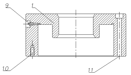
[0032] The housing 1 in Example 1 is shown in Figure 3, the housing 1 is a hollow cylindrical structure, the inner hole of the lower part of the housing 1 is larger than the inner hole of the upper part, and the inner diameter of the upper part is 4-4- 6mm, the housing 1 plays the role of guiding the drill pipe and the oil pipe. There is an oil filling hole 9 on the outer circle of the upper part of the housing 1. Grease is injected into each bearing in the housing 1 through the oil filling hole 9 .
[0033] There are threaded holes 10 on the lower surface of the housing 1 , and the pressure plate 6 is fixedly connected to the threaded holes 10 on the lower surface of the housing 1 through fixing bolts 8 .
[0034] The casing 1 also has several bolt holes 11, which run through the casing 1, and the rotary self-sealing sealing device can be fixed on the wellhead flange, wellhead cross or blowout preventer and other supporting facilities through the bolt holes 11.
Embodiment 3
[0036] The upper bearing 2 in Embodiment 1 is shown in Figure 4. The upper bearing 2 is composed of a lower pressure ring 12, an upper pressure ring 13 and an upper bearing ball body 14. Both the lower pressure ring 12 and the upper pressure ring 13 are ring-shaped pressure rings. Ring, the upper bearing ball body 14 is placed between the lower pressure ring 12 and the upper pressure ring 13.
[0037] There is an annular boss on the lower end surface of the lower pressure ring 12, and the boss cooperates with the groove of the corresponding part of the rotary self-sealing rubber sleeve 5 to trap and compress the rubber sleeve, and at the same time, play a sealing role.
PUM
 Abstract
Description
Claims
Application Information
 - R&D
- Intellectual Property
- Life Sciences
- Materials
- Tech Scout
- Unparalleled Data Quality
- Higher Quality Content
- 60% Fewer Hallucinations
Browse by: Latest US Patents, China's latest patents, Technical Efficacy Thesaurus, Application Domain, Technology Topic, Popular Technical Reports.
© 2025 PatSnap. All rights reserved.Legal|Privacy policy|Modern Slavery Act Transparency Statement|Sitemap|About US| Contact US: help@patsnap.com