Supercharge Your Innovation With Domain-Expert AI Agents!

All-positioning connecting rod

A technology of connecting rods and positioning grooves, which is applied to connecting rods, shafts, bearings, mechanical equipment, etc., can solve problems such as low yield strength and fatigue strength, irregular joint surfaces, and high material brittleness, and achieve high shear resistance, The effect of high assembly quality

Inactive Publication Date: 2011-05-18
潍坊浩泰机械有限责任公司
View PDF6 Cites 0 Cited by
  • Summary
  • Abstract
  • Description
  • Claims
  • Application Information

AI Technical Summary

Problems solved by technology

Expansion processing makes the joint surface between the end of the cracked connecting rod cover and the end of the crank mounting seat have a fully meshed staggered structure, which improves the joint quality of the joint surface and does not need to be processed on the joint surface, which improves the connecting rod. The bearing capacity, shear resistance, and assembly quality have been improved, but the joint surface of the expansion processing is irregular, which destroys the internal metallographic structure. After the expansion, the deformation of the connecting rod cover and the crank mounting seat is inconsistent, and 0.01mm is generated when the positioning is repeated. The deviation between left and right affects the accuracy of repeated assembly. At the same time, the materials used in the bursting process are brittle, expensive, and have low yield strength and fatigue strength.

Method used


Image

  • All-positioning connecting rod
  • All-positioning connecting rod
  • All-positioning connecting rod

Examples


Embodiment Construction

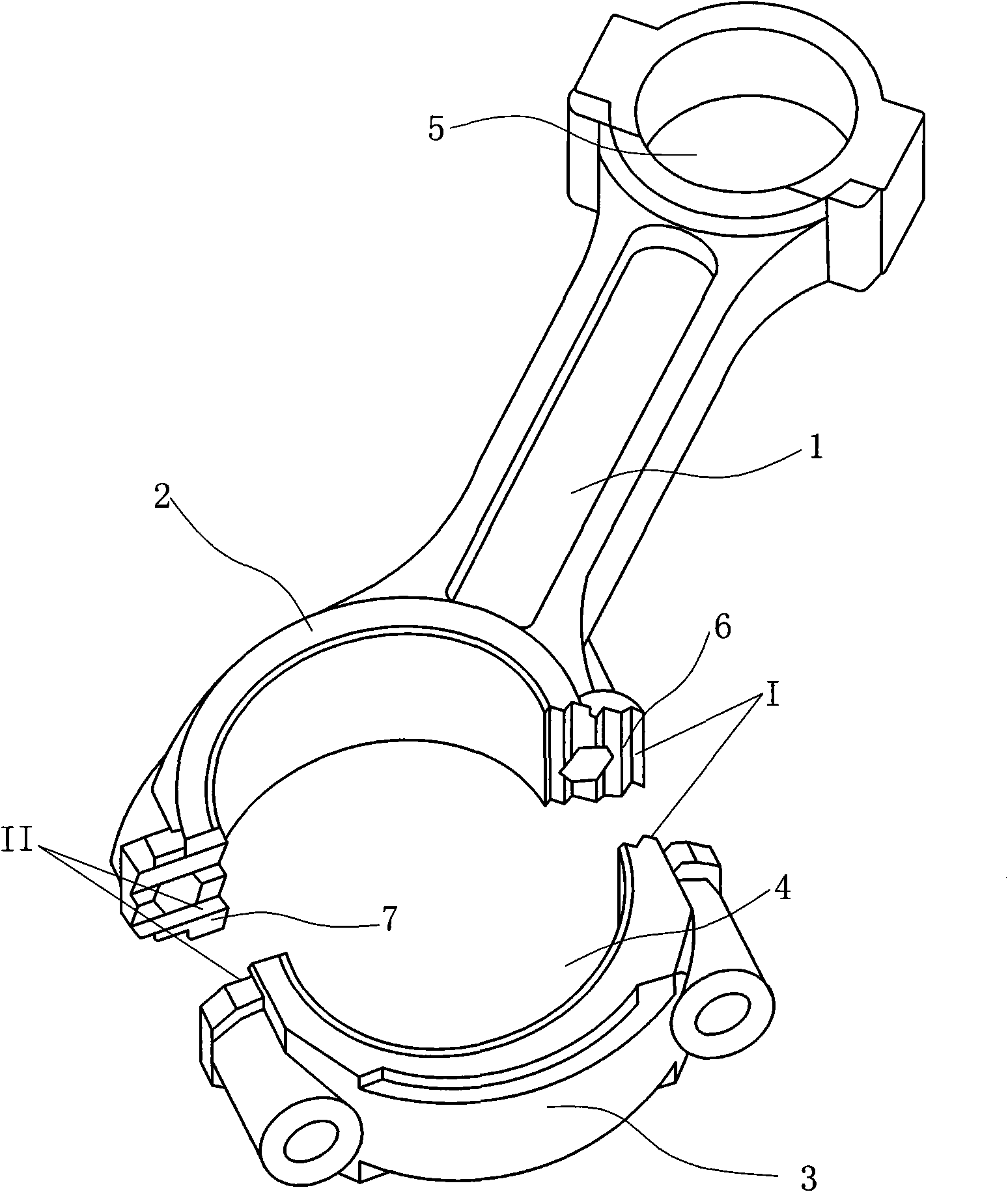
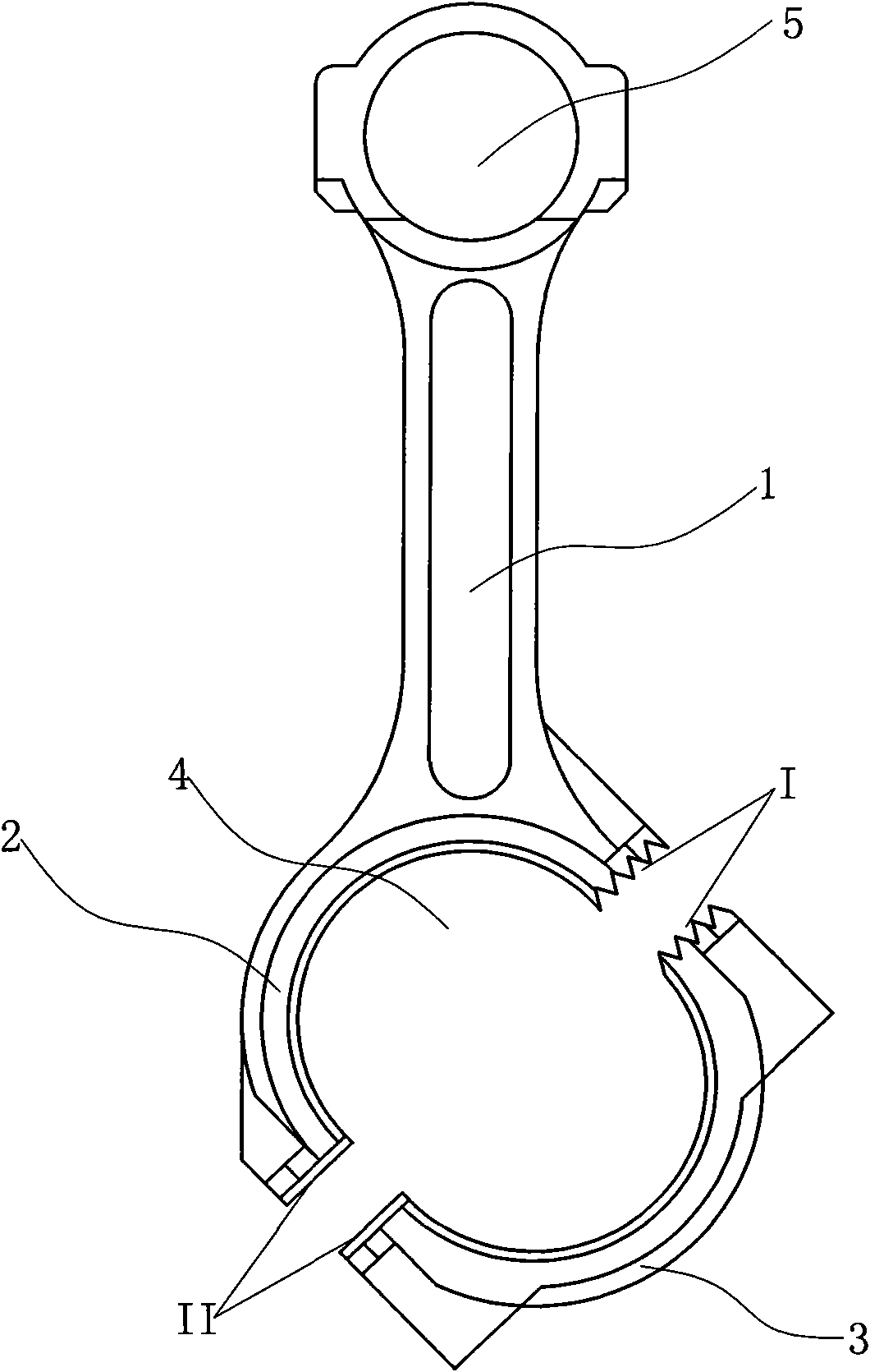
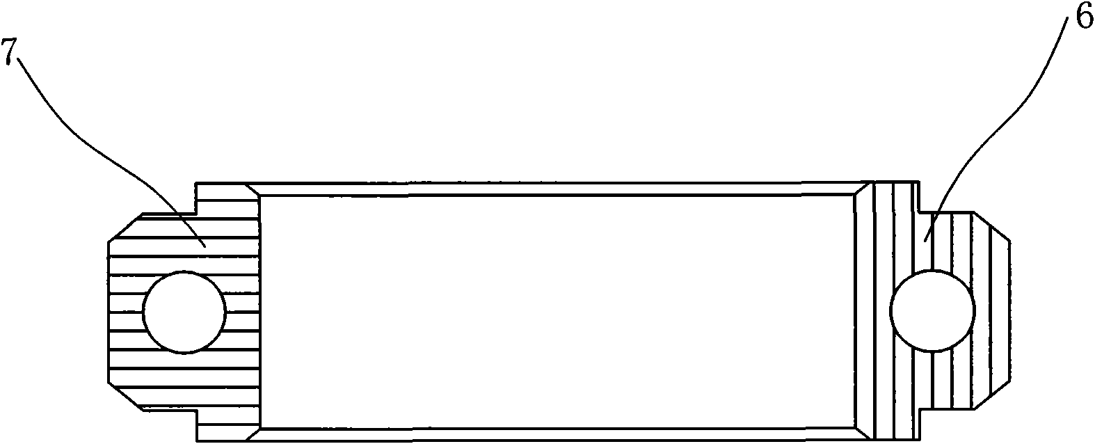
[0016] like figure 1 , figure 2 and image 3 As shown, the full positioning connecting rod includes a connecting rod body 1, and one end of the connecting rod body 1 is provided with a crank mounting seat 2, and a connecting rod cover 3 is installed on the crank mounting seat 2, and the crank mounting seat 2 and The connecting rod cover 3 forms a crank hole 4 for connecting the crank, the other end of the connecting rod body 1 is provided with a piston pin hole 5 for connecting the piston, the crank mounting seat 2 and the end of the connecting rod cover 3 There is a first coupling surface I and a second coupling surface II between them, the first coupling surface I is provided with a first positioning groove 6 which cooperates with each other, and the second coupling surface II is provided with a second positioning groove 6 which cooperates with each other. Groove 7, the first positioning groove 6 and the second positioning groove 7 are not parallel, the intersection point...


PUM


Abstract

The invention relates to an all-positioning connecting rod, which comprises a connecting rod body, wherein one end of the connecting rod body is provided with a crank installing seat, a connecting rod cover is arranged on the crank installing seat, the crank installing seat and the connecting rod cover form a crank hole of a connecting crank, the other end of the connecting rod body is provided with a piston pin hole for connecting a piston, a first joint surface and a second joint surface are arranged between end parts of the crank installing seat and the connecting rod cover, a first positioning groove mutually matched with the first joint surface is arranged on the first joint surface, a second positioning groove mutually matched with the second joint surface is arranged on the second joint surface, and the first positioning groove and the second positioning groove are not in parallel; and the first positioning groove and the second positioning groove are not in parallel, and restrict the crank installing seat and the connecting rod cover to relatively move along the axial direction of the crank hole and relatively move along the radial direction of the crank hole, thus the bearing capacity, the resistance to shear and the assembling quality of the connecting rod are higher.

Description

technical field [0001] The invention relates to the field of engine accessories, in particular to a connecting rod. Background technique [0002] The connecting rod includes a crank hole formed by a crank mounting seat and a connecting rod cover at one end of the connecting rod body and a piston pin hole at the other end of the connecting rod body. The connecting rod is arranged between the piston and the crankshaft to transmit the force of the piston to the crankshaft. Thereby converting the reciprocating motion of the piston into the rotary motion of the crankshaft. The connecting rod bears high periodic impact force, bending force and inertial force in the working process. This requires the connecting rod to have high strength, toughness and fatigue performance. The positioning groove between the crank mounting seat and the connecting rod cover of the existing connecting rod can only constrain the radial movement of the crank mounting seat and the connecting rod cover a...

Claims


Application Information

Patent Timeline
Patent Type & Authority Applications(China)
IPC IPC(8): F16C7/02
Inventor 吕继贤蒲光明
Owner 潍坊浩泰机械有限责任公司
Features
  • R&D
  • Intellectual Property
  • Life Sciences
  • Materials
  • Tech Scout
  • Unparalleled Data Quality
  • Higher Quality Content
  • 60% Fewer Hallucinations
Learn More