Eureka AIR delivers breakthrough ideas for toughest innovation challenges, trusted by R&D personnel around the world.

Circular tube connector

A technology of connectors and round pipes, which is applied in the direction of sleeve/socket connections, pipes/pipe joints/fittings, couplings, etc., which can solve the problem of increasing the outer diameter of pipe joints, increasing the expansion process of pipe joints, and inappropriate structures and other problems, to achieve the effect of doubling the degree of sealing, reducing processing costs and improving appearance

Inactive Publication Date: 2013-12-11
翟秋朗 +1
View PDF3 Cites 0 Cited by
  • Summary
  • Abstract
  • Description
  • Claims
  • Application Information

AI Technical Summary

Problems solved by technology

It can be seen from the above structure that since the plug sleeve is pressed against the outer step of the pipe sleeve instead of the inner tooth locking ring, when the tube is removed, there is no reaction force on the outer edge of the inner tooth locking ring , it is likely to be the inversion of the shape rather than the elastic deformation in the design, resulting in an unsatisfactory pipe removal effect. In addition, after the round pipe is inserted into the pipe joint, it will also move backward because the inner tooth locking ring is not compressed, so the structure There are obvious loopholes and inadequacies
[0005] Chinese patent application 200810133606.7 discloses a fluid pipe connection device and its matching pipe removal tool. There are three obvious steps on the inner wall of the pipe joint port from the inside to the outside. The first step is the limit of the insertion depth of the round pipe, and the second The step is where the sealing ring is placed. The third step is assembled with the push gear ring, the inner tooth snap ring and the support ring by the plug sleeve, and then placed on the end face of the third step, and then riveted by the pipe wall. Fixed, the outer diameter of the plug sleeve is larger than the outer diameter of the inner tooth snap ring and the supporting ring, and the thickness of the pipe wall is larger. The supporting ring and the plug sleeve are supported by the third step. This structure adds one level Steps increase the expansion process of the pipe joint. It is not necessary to add an outer wall to the plug sleeve to wrap the inner tooth snap ring and the support ring. Instead, the outer diameter of the pipe joint increases, which brings about the disadvantage of occupying space.
[0006] The above-mentioned prior art has the following disadvantages: (1) the interface generally has more than two obvious steps from the inner wall to the outer edge of the port, which undoubtedly increases the work for the production of connecting pipe fittings with thin-walled stainless steel pipes, resulting in subsequent The outer diameter of the connector increases, making it unsightly when the pipeline is exposed and exposed, and inconvenient when it is hidden.
(2) The method of screwing the pressure sleeve is not suitable for the selection of the interface made of thin-walled stainless steel pipes. Compared with the internal riveting seal, it is more complicated and more costly
(3) Some composition and arrangement are unreasonable. For example, the inner port of the pressure sleeve does not directly compress the circlip but against the circlip support, causing the round tube to move outward after being pushed in.

Method used


Image

  • Circular tube connector
  • Circular tube connector
  • Circular tube connector

Examples


Embodiment 1

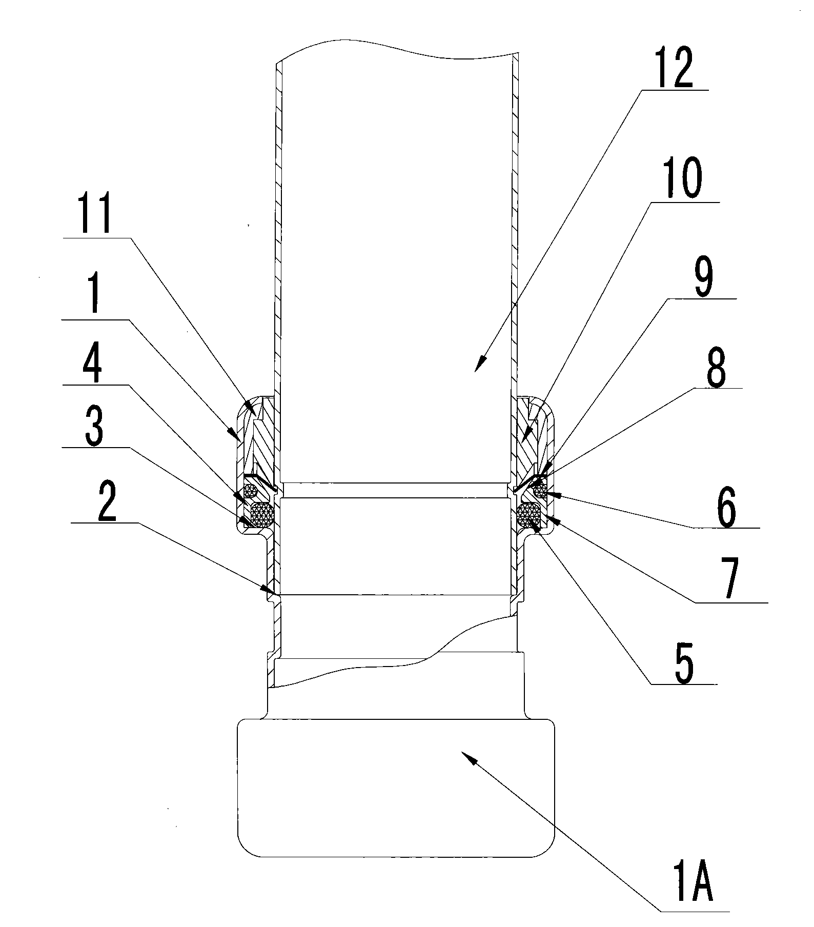
[0031] Embodiment 1 is the embodiment in which an inner sealing ring and an outer sealing ring are arranged on the inner wall and the outer wall of the circlip supporting body respectively: please refer to figure 1 , Figure 10 , including straight-through round pipe connector body 1A, interface 1, first step 2, second step 3, circlip support body 4, inner sealing ring 5, outer sealing ring 6, round tube pin 7, inner cone 8, and circlip 9, snap spring supports 10, pressure sleeve 11, round pipe 12.

[0032] Such as figure 1 As shown: a straight-through round pipe connector body 1A is placed vertically, and the interface 1 for the insertion of the round pipe 12 is provided upwards, and the first step that limits the insertion depth of the round pipe 12 is provided in the interface 1 from bottom to top in the axial direction 2. Place the circlip supporting body 4, the inner seal ring 5, the outer sealing ring 6, the circlip 9, the circlip support 10, the second step 3 of the p...

Embodiment 2

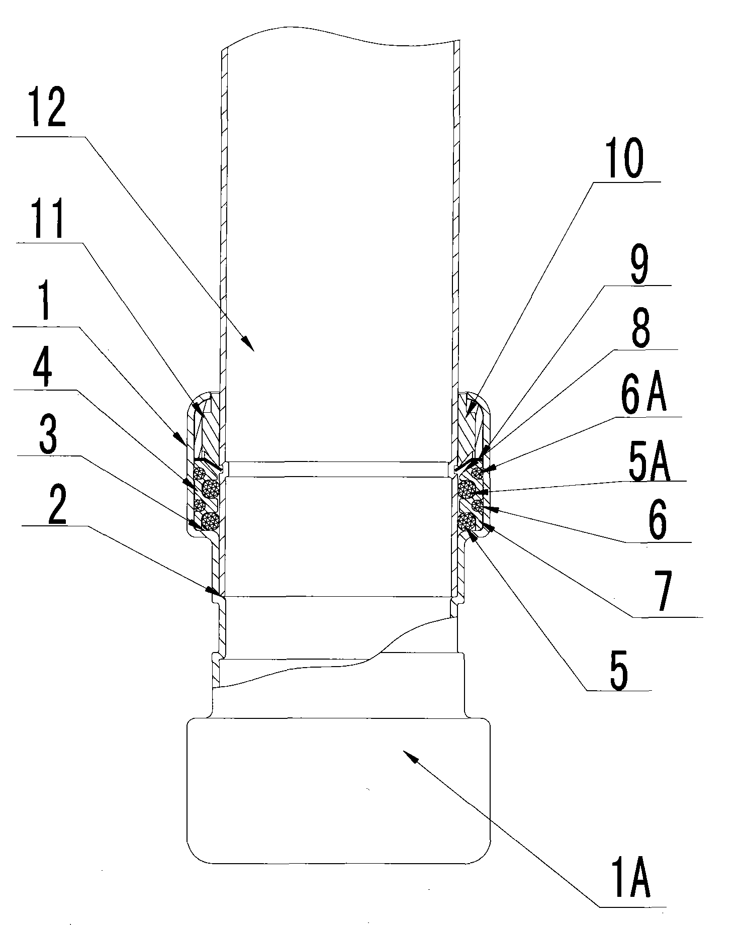
[0033] Embodiment 2 is an implementation mode in which more than one inner sealing ring and outer sealing ring are arranged on the inner wall and outer wall of the circlip supporting body: please refer to figure 2 , Figure 10 , including interface 1, first step 2, second step 3, circlip support body 4, inner sealing ring 5, inner sealing ring 5A, outer sealing ring 6, outer sealing ring 6A, round pin 7, inner cone 8, Circlip 9, circlip support 10, pressure sleeve 11, round pipe 12.

[0034] Such as figure 2 As shown, the second embodiment is similar to the first embodiment, except that the axial dimension of the circlip supporting body 4 is appropriately increased, and at the same time, a groove is respectively added on the inner wall and the outer wall, and the corresponding inner sealing ring 5A and outer sealing ring 6A are arranged respectively. , the rest of the structures and functions are the same as those in Embodiment 1.

Embodiment 3

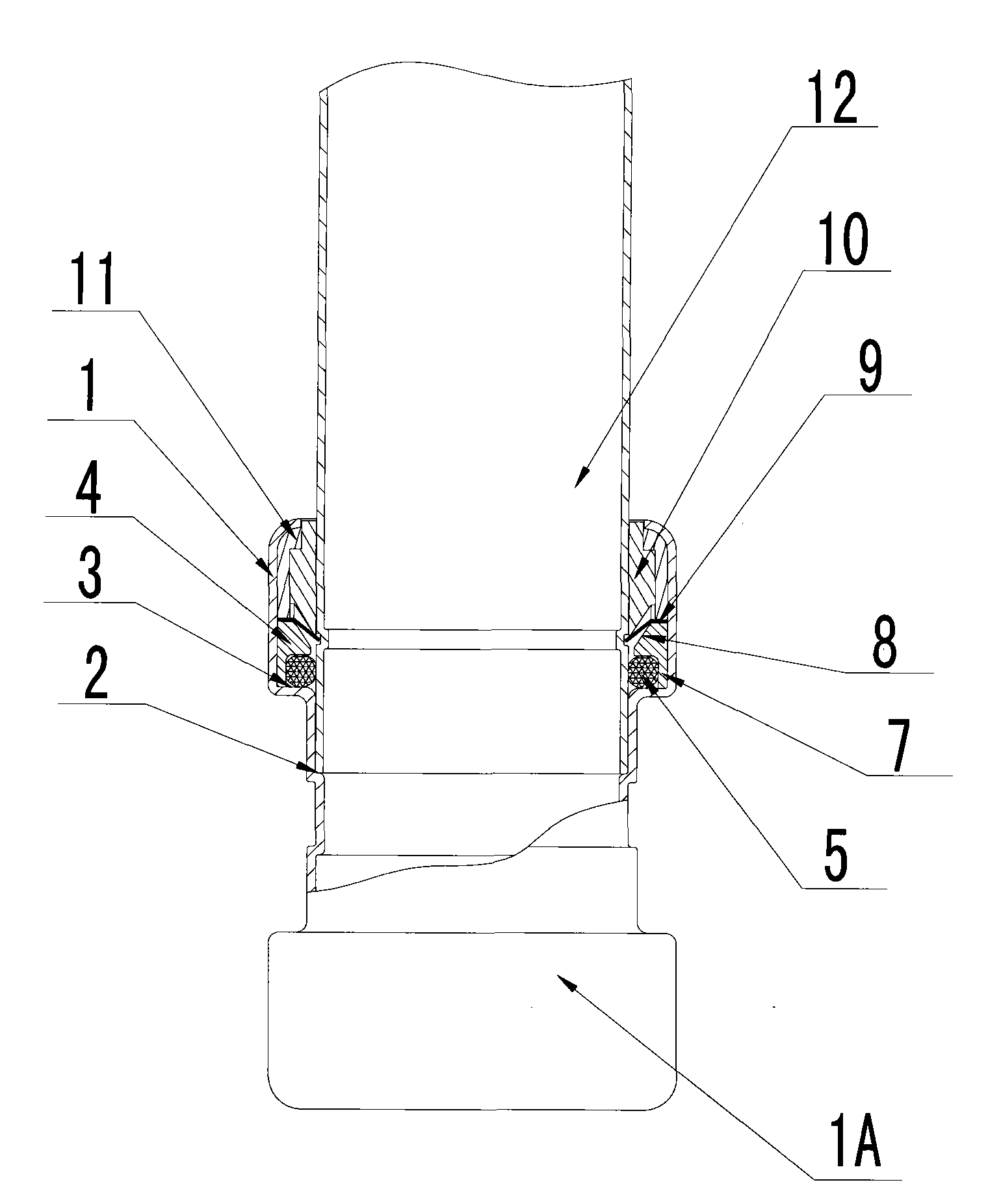
[0035] Embodiment 3 is the embodiment in which the inner sealing ring is only placed on the inner wall of the circlip supporting body: please refer to image 3 , Figure 10 , including interface 1, first step 2, second step 3, circlip support body 4, inner sealing ring 5, round tube pin 7, inner cone 8, circlip 9, circlip support 10, pressure sleeve 11, round tube 12.

[0036] Such as image 3 As shown, the difference between the third embodiment and the first embodiment is that the outer wall of the circlip supporting body 4 is not provided with a groove and no outer sealing ring is installed, and the outer wall of the circlip supporting body 4 and the interface 1 are sealed in a tight fit. , the rest of the structures and functions are the same as those in Embodiment 1.


PUM


Abstract

A round tube connector comprising a connector body (1A), a lock washer seat (4), o-rings (5, 6), a lock washer (9), a lock washer support (10), and a pressure sleeve (11). The connector body (1A) has an interface (1) into which a round tube (12) can be inserted for connection. The lock washer seat (4), the o-rings (5, 6), the lock washer (9), the lock washer support (10), and the pressure sleeve (11) are packaged within the interface (1). The round tube connector is characterized in that the lock washer seat (4), the lock washer (9), and the pressure sleeve (11) have the same external diameter and are axially abutting one with the next from the inside outward. In the round tube connector, the structure of the lock washer seat reduces the external diameter of the interface. The external opening of the lock washer support protrudes out of the outer surface of the pressure sleeve or is slightly indented with respect to the open portion of the interface.

Description

technical field [0001] The invention relates to a connecting pipe fitting which can be used for pipe installation in liquid and gas supply and discharge systems, in particular to a circular pipe connector. Background technique [0002] Pipelines and their installation and connection technologies are widely used in daily life, such as water supply and drainage pipeline systems, gas supply pipeline systems, etc. Pipeline connection accessories are constantly being innovated and improved with the continuous updating and application of pipeline materials. Traditional plating Zinc water pipes, aluminum-plastic pipes and plastic water supply pipes are gradually being eliminated due to their environmental protection and unsatisfactory sanitation. In recent years, with the popularization and use of stainless steel pipes and copper pipes (mostly in foreign countries), many pipe connection technologies and their products have been born and appeared, such as press-type and plug-in pipe...

Claims


Application Information

Patent Timeline
Patent Type & Authority Patents(China)
IPC IPC(8): F16L21/02
CPCF16L37/091F16L37/0915
Inventor 翟秋朗翟伟军
Owner 翟秋朗
Why Eureka
Eureka Blog
Learn More