Electric tilt antenna and base station

An electronically adjustable antenna and antenna technology, which is applied to antennas, antenna coupling, antenna unit combinations with different polarization directions, etc., can solve the problem of high cost and achieve the effect of large coverage

Active Publication Date: 2011-05-18
MOBILE ANTENNA TECH SHENZHEN +5
View PDF5 Cites 34 Cited by
  • Summary
  • Abstract
  • Description
  • Claims
  • Application Information

AI Technical Summary

Problems solved by technology

[0005] The purpose of the embodiments of the present invention is to provide an electronically adjustable

Method used


Image

  • Electric tilt antenna and base station
  • Electric tilt antenna and base station
  • Electric tilt antenna and base station

Examples


Embodiment 1

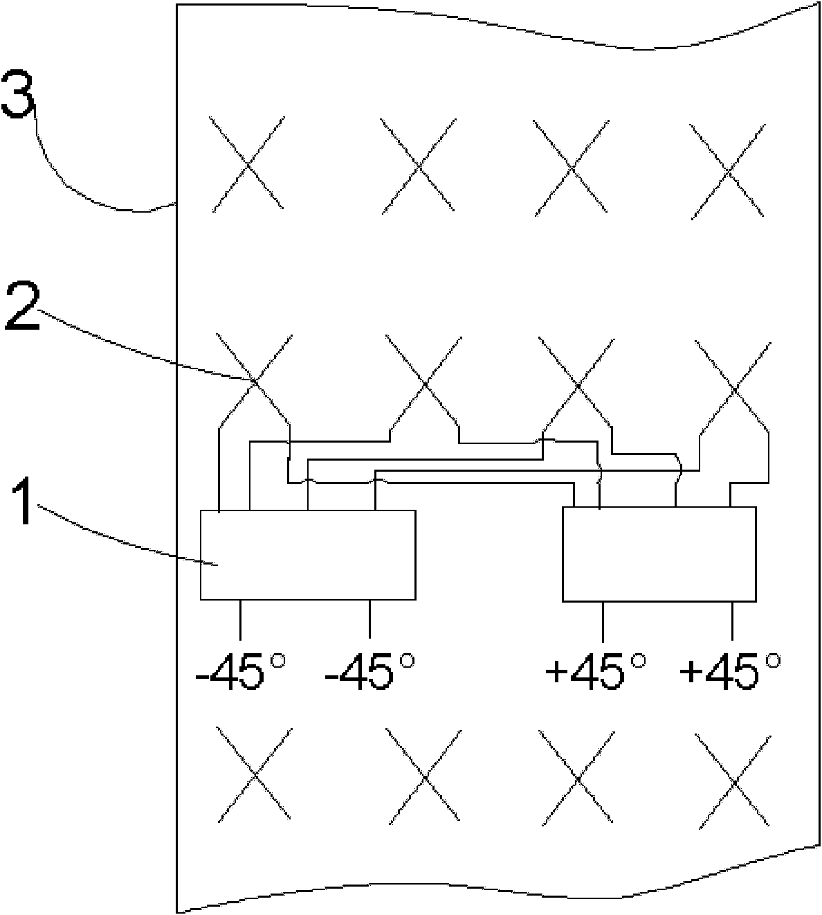
[0028] see Figure 1 to Figure 4 , an electrically adjustable antenna provided by an embodiment of the present invention, comprising:

[0029] The antenna reflector 3 used to adjust the beam, which is placed in parallel from top to bottom and fixed together through the pillars, and the phase shift of the non-equal-amplitude Butler matrix used to offset the beam to form two beams with a predetermined angle Network 1 and assembly;

[0030] The upper surface of the antenna reflector 3 is equipped with four rows of dual-polarized radiation units 2 for transmitting and receiving electromagnetic waves;

[0031] The assembly includes a feed network with a phase shifting function and a transmission structure for adjusting the electronic downtilt angle connected together.

[0032] In an embodiment of the present invention, the phase-shifting network 1 of the non-constant-amplitude Butler matrix can be affixed together with the antenna reflector 3 through the first pillar; The phase ...

Embodiment 2

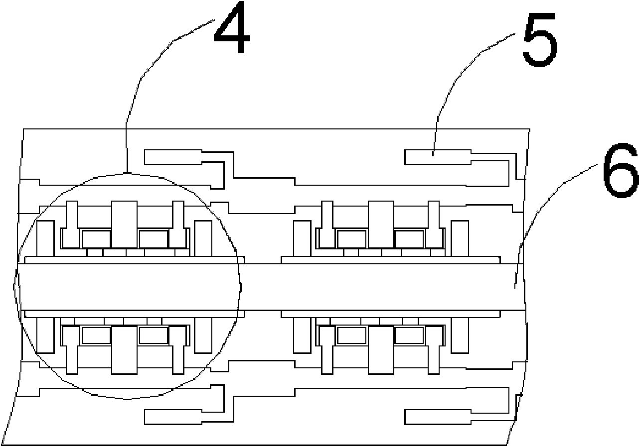
[0038] In an embodiment of the present invention, the feed network with phase shifting function specifically includes:

[0039] A transmission line 5 made of a metal cutting board or a PCB board for use as a feeder network;

[0040] A phase shifter 4 that can move relatively on the transmission line 5 for phase shifting.

[0041] The transmission structure specifically includes:

[0042] A connecting rod 6 connected to the phase shifter 4 for driving the phase shifter 4;

[0043] A rotating structure 7 connected with the connecting rod 6 .

[0044] In the embodiment of the present invention, when the rotating mechanism 7 rotates, it can drive the connecting rod 6 to move, and then drive the phase shifter 4 to move, thereby changing the contact area between the phase shifter 4 and the transmission line 5, thereby realizing the phase shifting function.

[0045] In the embodiment of the present invention, the two ends of the phase shifter 4 can be moved away from and close to ...

Embodiment 3

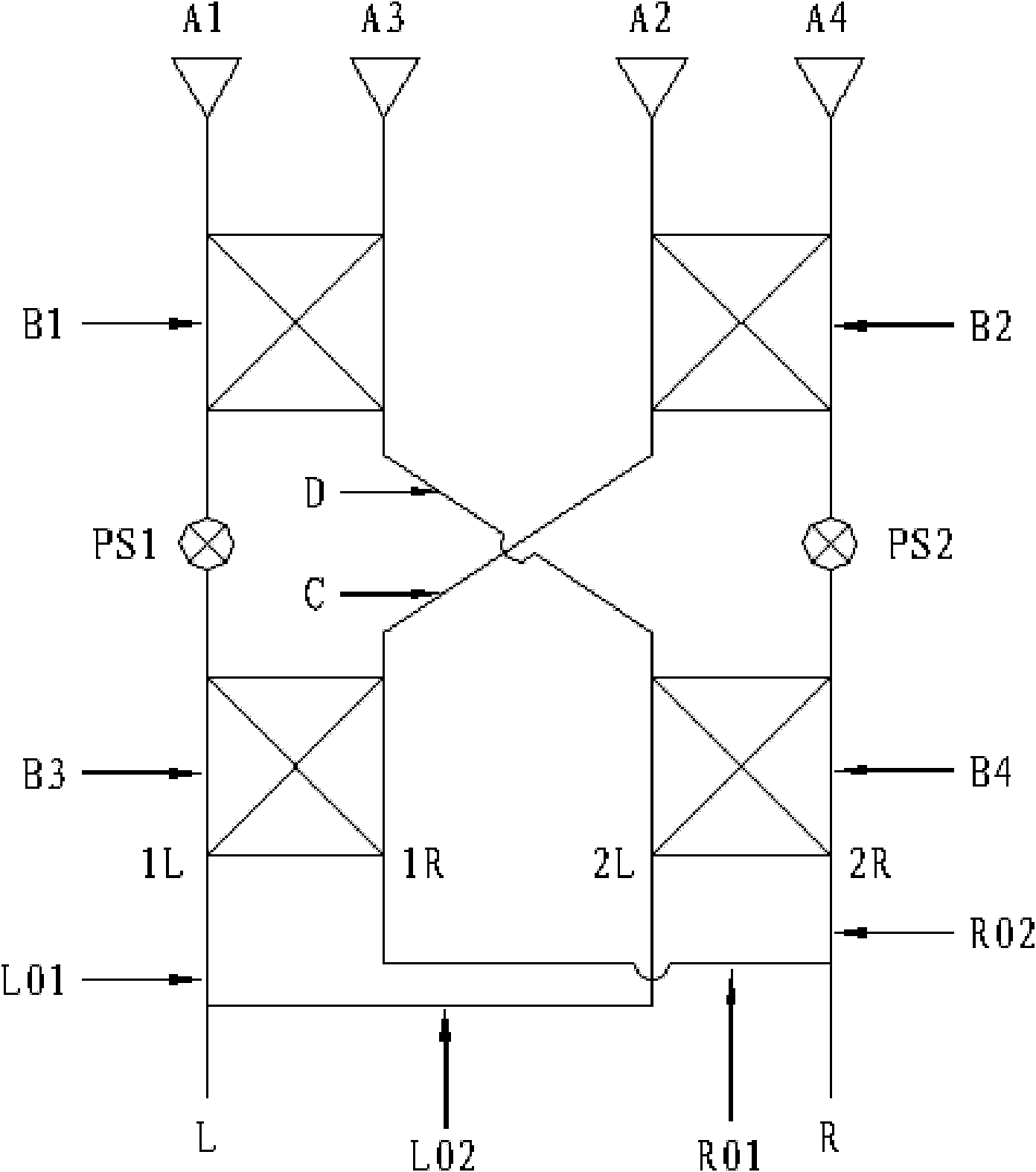
[0048] In an embodiment of the present invention, the phase-shifting network 1 of the non-constant-amplitude Butler matrix specifically includes:

[0049] The first 3dB90 degree bridge B1, the second 3dB90 degree bridge B2, the third 3dB90 degree bridge B3 and the fourth 3dB90 degree bridge B4;

[0050] Two sections of 0.125 vacuum wavelength transmission lines PS1 and PS2 with phase shifting function;

[0051] Two connectors C and D;

[0052] two unequal power splitters that are respectively connected to the first radio frequency signal input port L and the second radio frequency signal input port R;

[0053] Two output terminals L01 and L02 of one divided into two unequal power dividers are respectively connected to an input terminal 1L and 2L of the third 3dB90 degree electric bridge B3 and the fourth 3dB90 degree electric bridge B4;

[0054] The two output terminals R01 and R02 of another unequal power divider divided into two are respectively connected to the other inpu...


PUM


Abstract

The invention is suitable for the field of antennae, and provides an electric tilt antenna and a base station. The electric tilt antenna comprises an antenna reflector used for adjusting wave beams, a phase shift network of an unequal-amplitude Butler matrix used for shifting the wave beams to form two wave beams having a preset included angle, and an assembly, wherein the antenna reflector, the phase shift network and the assembly are parallelly arranged from top to bottom and fixedly connected together through supports; the upper surface of the antenna reflector is provided with four rows of bipolar radiation units used for transmitting and receiving electromagnetic waves; and the assembly comprises a feed network with phase shift function and a transmission structure used for adjustingan electronic down tilt, which are connected together. The phase shift network of the unequal-amplitude Butler matrix shifts the wave beams to generate two independent wave beams having the preset included angle, so that a single sector can be upgraded into two sectors under the condition of not obviously influencing adjacent base stations; therefore, the aims of widening a coverage area and expanding capacity are fulfilled.

Description

technical field [0001] The invention belongs to the field of antennas, in particular to an electric adjustable antenna and a base station. Background technique [0002] In the current wireless communication field, what is most lacking is spectrum resources. In order to effectively utilize limited spectrum resources, the concept of "cellular" is introduced in network construction. In order to cover a large area, the area is first divided into many small cellular areas, so that the same spectrum resources can be used in distant "cells", achieving the effect of spectrum reuse. [0003] With the increase of mobile users and call volume, network expansion has become urgent. The traditional expansion method is the so-called cell splitting, that is, to reduce the coverage area of ​​the existing "cell" and introduce a new "cell" in the newly generated coverage blind area. Therefore, the operator must pay a high cost price for cellular splitting, whether it is an increased base st...

Claims


Application Information

Patent Timeline
IPC IPC(8): H01Q1/36H01Q1/52H01Q3/30H01Q3/32H01Q19/10H01Q21/24H04W88/08
Inventor 彭燕王炳烽骆胜军曾志
Owner MOBILE ANTENNA TECH SHENZHEN
Why Eureka
Try Eureka