

Data transmission method and device
A data transmission method and data technology, applied in the field of communication, can solve problems such as inability to select an antenna, reduce system performance, etc., and achieve the effect of improving performance
- Summary
- Abstract
- Description
- Claims
- Application Information
AI Technical Summary
Problems solved by technology
Method used
Image


Examples
Embodiment 1
[0043] In this embodiment, the sending end selects the antenna for sending data and sends data to the receiving end according to the following steps for each receiving end:
[0044] Step 1, the mode acquisition module 10 selects the multi-antenna data transmission mode as space diversity according to the channel state information;
[0045] Specifically, it may be to calculate the spectral efficiency of each multi-antenna data transmission mode, and select the multi-data transmission mode with the largest spectral efficiency as the current data transmission mode, wherein, in this embodiment, the spectral efficiency of the space diversity is the largest, and the space diversity Mode is the current data sending mode.
[0046] Step 2, the antenna selection module 20 selects M antennas with the largest mutual spacing in space according to the results obtained by the mode acquisition module 10, and the difference in the number of M antennas in each polarization direction is not grea...
Embodiment 2
[0054] In this embodiment, the sending end selects the antenna for sending data and sends data to the receiving end according to the following steps for each receiving end:
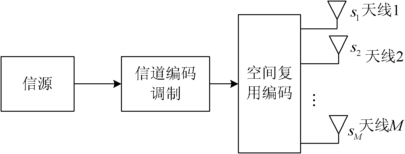
[0055] Step 1, the mode acquisition module 10 selects the data transmission mode of the multi-antenna as spatial multiplexing according to the channel state information;
[0056] For example, the mode acquisition module 10 may calculate the spectrum efficiency of each multi-antenna data transmission mode, and select the multi-antenna data transmission mode with the largest spectrum efficiency as the current data transmission mode. Wherein, in this embodiment, the spectral efficiency of spatial multiplexing is the largest, and the spatial multiplexing mode is selected as the current data transmission mode.
[0057] Step 2, the antenna selection module 20 selects the M antennas that are farthest from each other in space according to the results of the mode acquisition module, and the difference in the numbe...
Embodiment 3
[0065] In this embodiment, the sending end selects the antenna for sending data and sends data to the receiving end according to the following steps for each receiving end:
[0066] Step 1, the mode acquisition module 10 selects the current data transmission mode as cyclic delay diversity according to the channel state information;
[0067] For example, the mode acquisition module 10 can calculate the spectral efficiency of each multi-antenna data transmission mode, and select the multi-antenna data transmission mode with the largest spectral efficiency as the current data transmission mode. In this embodiment, the spectral efficiency of cyclic delay diversity Maximum, select the cyclic delay diversity mode as the current data transmission mode;
[0068] Step 2, the antenna selection module 20 selects the M antennas that are farthest from each other in space according to the results of the mode acquisition module, and the difference in the number of the M antennas in each pola...
PUM
 Abstract
Description
Claims
Application Information