Aluminum profile hot-extrusion shunt combined die structure

A combined mold and hot extrusion technology, which is applied in the direction of metal extrusion molds, etc., can solve the problems of increasing cost and affecting the strength of the mold, and achieve the effects of reducing openings, increasing strength, and reducing production costs

Inactive Publication Date: 2011-05-25
SHANGHAI RUISILE COMPOSITE METAL MATERIALS +2
View PDF0 Cites 2 Cited by
  • Summary
  • Abstract
  • Description
  • Claims
  • Application Information

AI Technical Summary

Problems solved by technology

[0004] In order to solve the technical problem that the upper and lower dies of the aluminum profile hot extrusion split flow combination die respectively open positioning pin holes and screw holes in the prior art, which further affects the strength of the die and

Method used


Image

  • Aluminum profile hot-extrusion shunt combined die structure
  • Aluminum profile hot-extrusion shunt combined die structure
  • Aluminum profile hot-extrusion shunt combined die structure

Examples


Embodiment Construction

[0015] The present invention will be further described below in conjunction with the accompanying drawings.

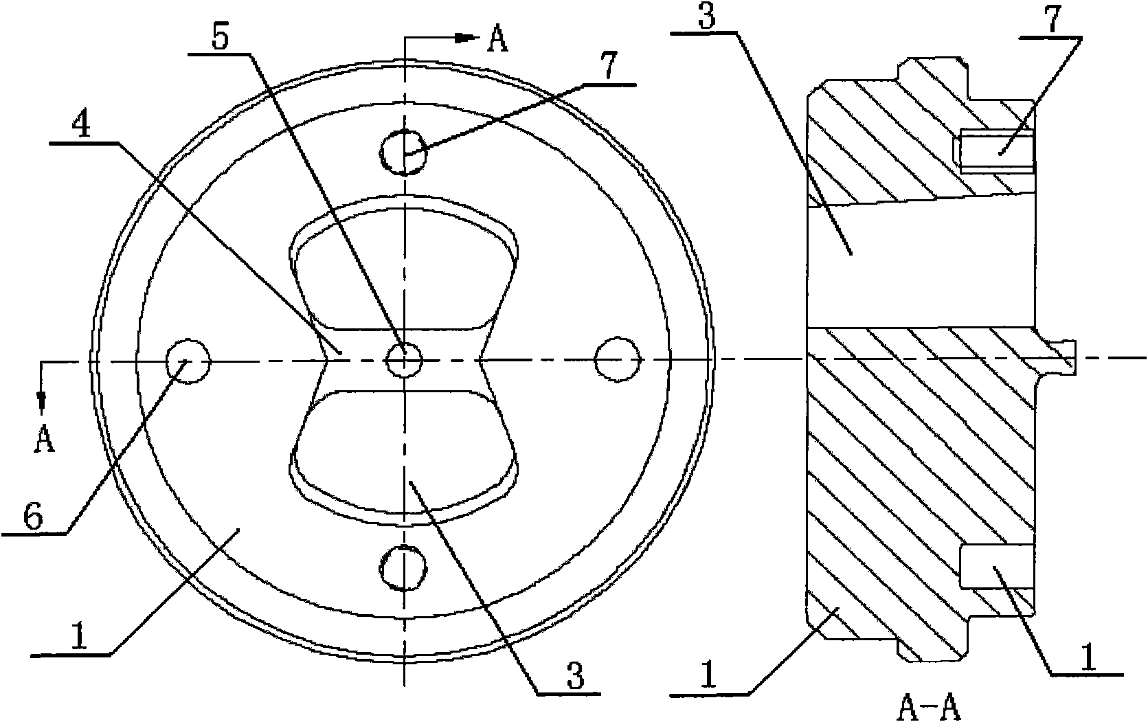
[0016] Such as figure 1 As shown, the upper mold 1 is provided with a shunt hole 3, a shunt bridge 4, and a mold core 5; the shunt hole 3 is a channel for the metal to lead to the lower mold hole, and the shunt bridge 4 is a bracket supporting the mold core 5, and the mold core 5 is used to Form the shape and size of the cavity of the profile.

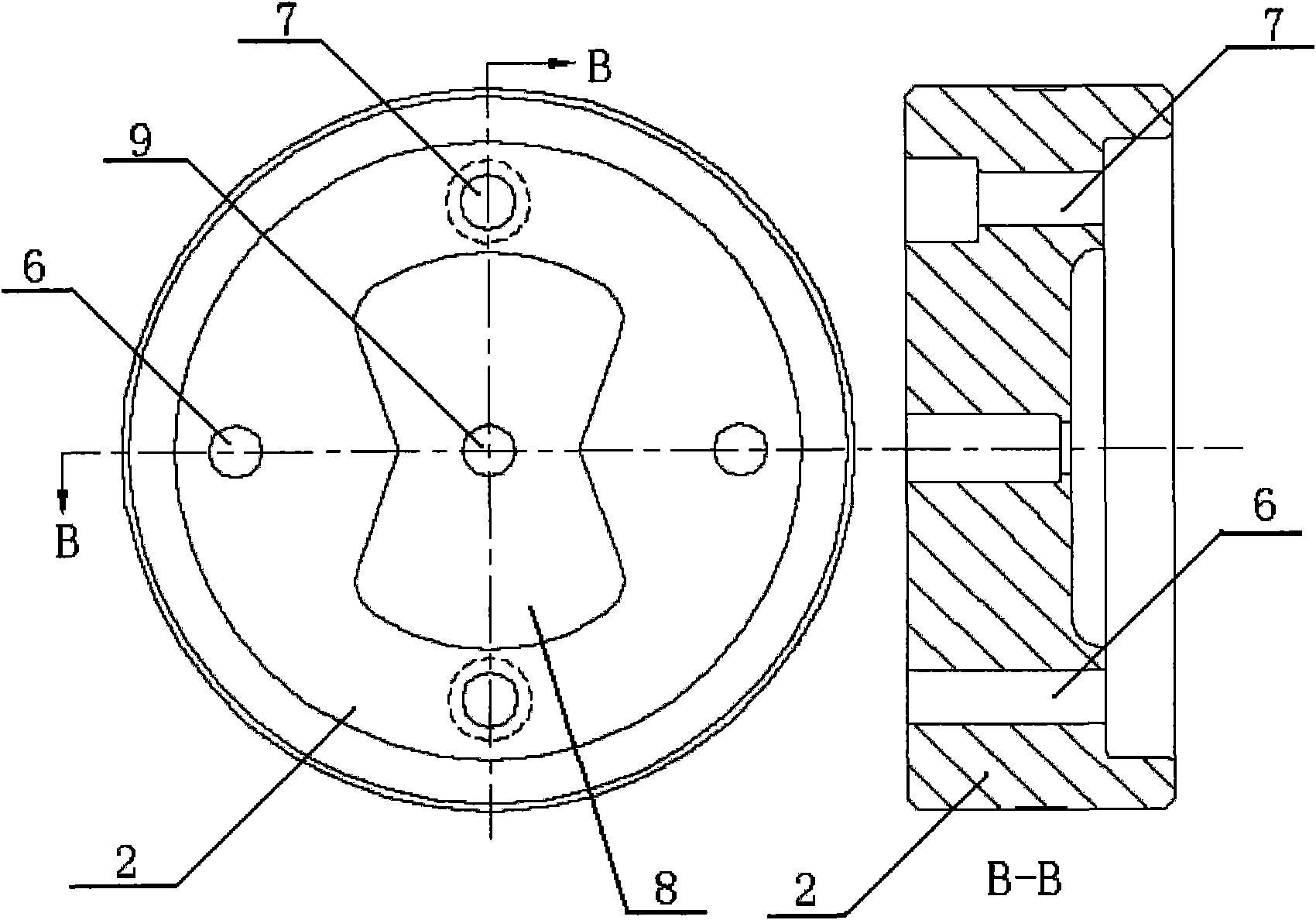
[0017] Such as figure 2 As shown, there is a welding chamber 8 and a mold cavity 9 on the lower mold 2; the welding chamber 8 gathers the metal flowing out of the shunt hole and welds them together again to form an integral material centered on the mold core 5. Continuous accumulation, static pressure constantly increases, until the metal is extruded out of the mold cavity 9.

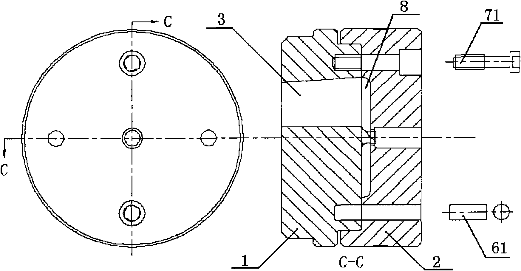
[0018] Such as figure 1 , figure 2 As shown, both the upper die 1 and the lower die 2 are provided with a set of screw holes 7 and a set of posit...


PUM


Abstract

The invention provides an aluminum profile hot-extrusion shunt combined die structure which comprises an upper die and a lower die. The upper die and the lower die are connected together through screws and provided with corresponding mounting holes; a cylinder-structured positioning pin is installed in every mounting hole; and the screws pass through the cylinder-structured positioning pins to fix the upper die and the lower die together. The invention has the advantages of compact and simple structure, convenience for machining, reduction of die size and production cost of aluminum profile.

Description

technical field [0001] The invention relates to an aluminum profile processing device, in particular to an aluminum profile hot-extrusion split flow combined die structure. Background technique [0002] Aluminum profile hot extrusion splitting combination die is widely used on extrusion machines without independent perforation system to produce pipes, hollow or semi-hollow aluminum profiles of various specifications and shapes. It usually consists of four parts: upper mold, lower mold, positioning pin and connecting screw, such as figure 1 , figure 2 with image 3 As shown; there are split holes, split bridges, and mold cores on the upper die; the split holes are the passages through which the metal leads to the type holes, and the split bridges are the brackets supporting the mold cores, which are used to form the shape and size of the profile cavity. The lower mold has a welding chamber, a die cavity, a working belt and an empty knife; the welding chamber gathers the m...

Claims


Application Information

Patent Timeline
IPC IPC(8): B21C25/02
Inventor 严荣庆郑晓军陈纪欢邹国林
Owner SHANGHAI RUISILE COMPOSITE METAL MATERIALS
Why Eureka
Try Eureka