Mold mechanism using inclined guide pillar and sliding block for secondary pushing out

A technology of mold mechanism and slider 2, applied in the field of injection molding mold and metal die-casting mold molding, can solve the problems of stuck in the mold, difficult to manufacture, and the spring cannot work immediately, and achieves good pressure transmission and convenient mold manufacturing. , The action is firm and reliable

Inactive Publication Date: 2011-05-25
牟维军
View PDF0 Cites 8 Cited by
  • Summary
  • Abstract
  • Description
  • Claims
  • Application Information

AI Technical Summary

Problems solved by technology

Because the above-mentioned mechanism has the following defects in actual production and manufacturing: it is inconvenient to manufacture, install and debug, such as the spring-type secondary push-out mechanism, due to the number of mold clamping, it is easy to break the spring, causing it to be stuck in the mold, or even damage the mold. Core and cavity
Another defect is that when the mold is just opened, the spring cannot work immediately, and after the mold is opened, the product cannot be demoulded. To realize this action, a fixed-distance parting mechanism must be installed, which will cause defects such as complicated mold mechanism and difficult manufacturing. , in order to avoid the defects in the above-mentioned mechanism, I combine my years of working experience in the mold design line to provide the following mold mechanism for secondary release

Method used


Image

  • Mold mechanism using inclined guide pillar and sliding block for secondary pushing out

Examples


Embodiment Construction

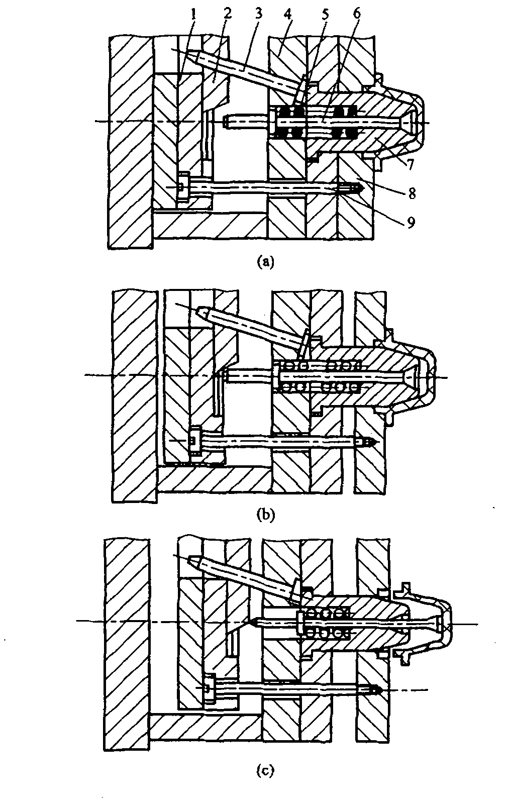
[0008] Shown in the figure is a mold mechanism that utilizes inclined guide posts and sliders for secondary extrusion. When the mold is clamped to the injection machine or die-casting machine, after injection or die-casting, the mold is opened, and the injection equipment or die-casting equipment completes the first push out, and at the same time, the inclined guide column 3 drives the slider 2 to move to the center of the mold. Figure C is the injection The ejector pin of the die-casting machine or die-casting machine continues to be ejected, and the slider pushes the center push rod 6 onto the slope of the slider, so that the pushing distance of the push rod 6 is ahead of the push rod 9, and the product is pushed out from the mold cavity plate 8 to complete the second time. Release, and the central push rod is reset by spring 5 simultaneously. When closing the mold, since the fixed model cavity plate is in contact with the movable model control plate 8, the movable model cav...


PUM


Abstract

The invention discloses a mold mechanism using an inclined guide pillar and a sliding block for secondary pushing out. The mold mechanism comprises mechanisms of a push rod fixing plate, the sliding block, the inclined guide pillar, a movable mold supporting plate, a spring, a center push rod, a mold core, a movable mold cavity plate, a push rod, a movable mold base plate, a fixed mold plate, a pouring gate bush and the like. The connection mode of the mold mechanism is that: the push rod fixing plate 1 is in clearance fit with the push rod 9; the push rod 9 is in clearance fit with the movable mold supporting plate 4 and is in slide fit with a mold core fixing plate; and then the push rod 9 is tightly connected with the movable mold cavity plate 8 by using screws. The sliding block 2 is in slide fit with the push rod fixing plate 1. The inclined guide pillar 3 is tightly fixed in an inclined hole of the movable mold supporting plate 4 and is in clearance fit with an inclined hole on the sliding block 2. The center push rod 6 is in clearance slide fit with the mold core, and the tail end is in slope movement with the sliding block 2. The mold core 7 is in clearance slide fit with the movable mold cavity plate 8, and the spring 5 is fixed in inner holes of the mold core 7 and the movable mold supporting plate 4. The mold mechanism is very reliable in motion, is simple in mold structure, and is suitable for molding injection molds and metal die-casting molds.

Description

technical field [0001] The invention relates to injection molding molds and metal die-casting molds, and is a mold structure that utilizes oblique guide posts and sliders for secondary extrusion. Background technique [0002] In the simple demoulding mechanism, no matter which type of demoulding mechanism is used, the pushing action of the product is completed at one time. However, some products are easily deformed or even damaged when they are pushed out at one time. Some products cannot automatically fall off after one push, or are difficult to take out from the cavity. Therefore, this type of product needs to be pushed out twice to disperse the demoulding resistance so that the product can be demoulded smoothly. This kind of mechanism that completes the demoulding of a product by two pushing actions is called a secondary demoulding mechanism. At present, the secondary demoulding mechanism used in the mold industry has the following types: A, single push plate secondary d...

Claims


Application Information

Patent Timeline
Patent Type & Authority Applications(China)
IPC IPC(8): B29C45/26B29C45/40B22D17/22
Inventor 牟维军
Owner 牟维军
Why Eureka
Try Eureka