
Method for erecting bridge

A technology for bridges and piers, which is applied in the field of bridge construction, and can solve the problems of bulky bridge girders, strong oppression, and impact on road traffic, and achieve the effects of reducing the height of structural buildings, avoiding ground-level operations, and reducing the elevation of bridge decks

Inactive Publication Date: 2011-05-25
SHANGHAI URBAN CONSTR DESIGN RES INST GRP CO LTD
View PDF5 Cites 4 Cited by
  • Summary
  • Abstract
  • Description
  • Claims
  • Application Information

AI Technical Summary

Problems solved by technology

The first method is a relatively common construction method at present, but the pier cover girder will be exposed, which not only affects the clearance under the bridge, but also affects the appearance of the bridge, especially the large cover girder, which will greatly increase the elevation of the bridge deck. The bridge cover girder is bulky and oppressive, and the landscape effect is poor
For the second method, although the cover beam can be eliminated and the elevation of the bridge deck can be reduced, it is necessary to build temporary supports within a limited range on both sides of the column for ground leveling work, which affects road traffic and is less safe

Method used


Image

  • Method for erecting bridge
  • Method for erecting bridge
  • Method for erecting bridge

Examples


Embodiment Construction

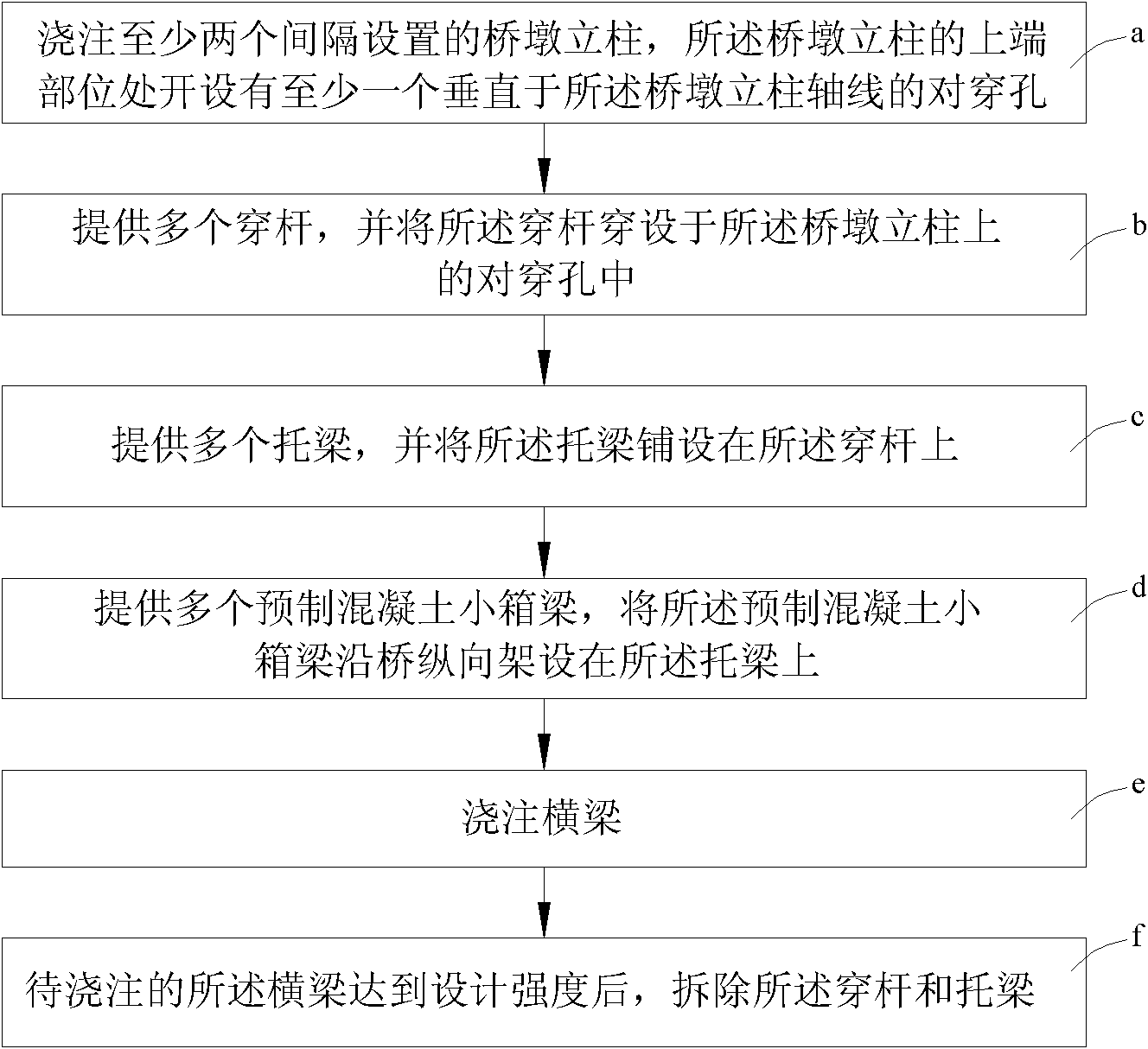
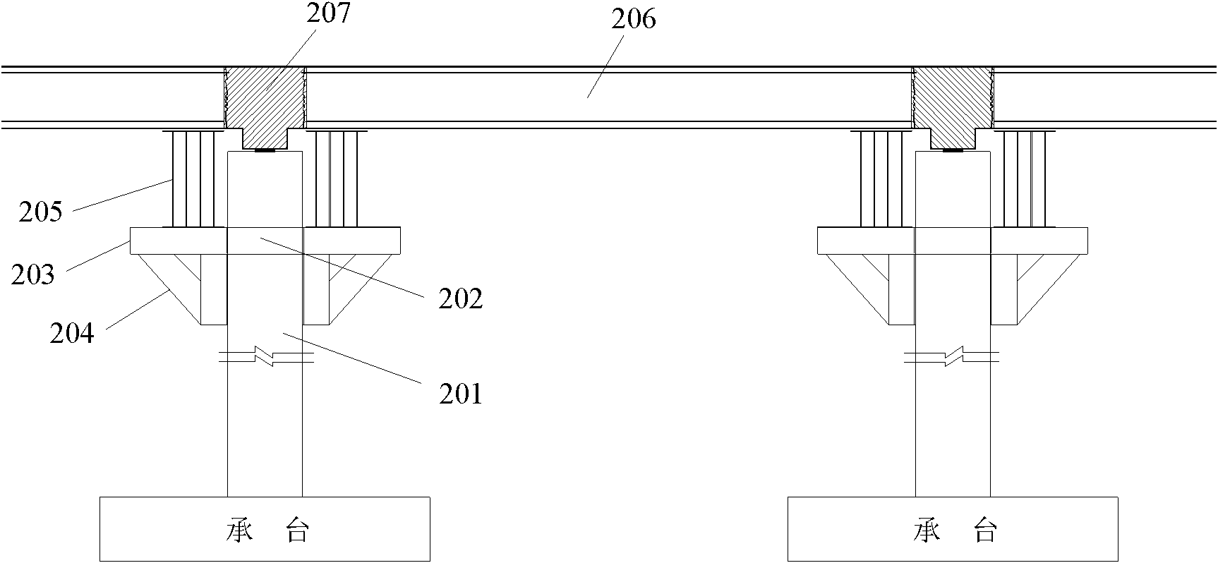
[0023] like figure 1 and figure 2 Shown is a flow chart of a bridge erection method provided by the present invention. The bridge erection method comprises the following steps:

[0024] a) pouring at least two pier columns 201 arranged at intervals, and at least one opposite perforation 202 perpendicular to the axis of the pier column is provided at the upper end of the pier column 201;

[0025] In this embodiment, the axis of the above-mentioned pair of through holes 202 is along the longitudinal direction of the bridge.

[0026] b) providing a plurality of piercing rods 203, and piercing the piercing rods 203 in the pair of piercing holes 202 on the pier column 201;

[0027] The piercing rod 203 is a steel box. In this embodiment, the width and height of the cross section of the steel box used for piercing the rod 203 are 0.8m and 0.8m respectively, and its wall thickness is 25mm.

[0028] The bridge erecting method also provides a plurality of triangular brackets 204 ,...


PUM

PropertyMeasurementUnit
Wall thicknessaaaaaaaaaa

Abstract

The invention discloses a method for erecting a bridge, which comprises the following steps: casting at least two bridge pier uprights at intervals, wherein at least one perforation hole vertical to the axis of the bridge pier upright is arranged on the upper end part of the bridge pier upright; providing multiple penetrating bars and penetrating the penetrating bars into the perforation hole on the bridge pier uprights; providing multiple supporting beams, and paving the supporting beams on the penetrating bars; providing multiple prefabricated concrete small box girders, and longitudinally erecting the prefabricated concrete small box girders on the supporting beams; casting cross beams; after the cast cross beams obtain the designed strength, dismantling the penetrating bars and the supporting beams. The construction method disclosed by the invention is simple, avoids horizontal work, does not influence the traffic on the ground, has relatively high safety reduces the bridge deck elevation, and can reduce the construction cost.

Description

technical field [0001] The invention relates to a bridge construction technology, in particular to a bridge erection method. Background technique [0002] At present, two methods are generally used when erecting overpass bridges in cities: one is simply supported first on the cover beam and then continuous; The first method is a relatively common construction method at present, but the pier cover beam will be exposed, which not only affects the clearance under the bridge, but also affects the appearance of the bridge, especially the large cover beam, which will greatly increase the elevation of the bridge deck. The bridge cover girders are bulky and oppressive, and the landscape effect is poor. For the second method, although the cover beam can be eliminated and the elevation of the bridge deck can be reduced, temporary supports need to be built within a limited range on both sides of the column for ground leveling work, which affects road traffic and is less safe. [0003...

Claims


Application Information

Patent Timeline
IPC IPC(8): E01D21/00
Inventor 周振兴闫兴非丁佳元黄锦源周良
Owner SHANGHAI URBAN CONSTR DESIGN RES INST GRP CO LTD
Learn More