Space crank rocker device

A crank rocker and crank technology, applied in the field of space crank rocker devices, can solve the problems of difficult cost reduction, unsatisfactory installation accuracy, complex structure, etc., and achieve the effects of low production and processing cost, guaranteed installation accuracy, and flexible orientation adjustment.

Inactive Publication Date: 2011-05-25
QINGDAO TECHNOLOGICAL UNIVERSITY
View PDF4 Cites 4 Cited by
  • Summary
  • Abstract
  • Description
  • Claims
  • Application Information

AI Technical Summary

Problems solved by technology

Although the quick return characteristic of the crank-rocker mechanism is beneficial to the machinery whose forward stroke is the working stroke and the return stroke is the empty stroke, it is harmful to the machinery whose forward stroke and return stroke are both working strokes; such as the shaking head mechanism of the electric fan, The pendulum mechanism of the air conditioner requires a crank-rocker mechanism with a pole angle of zero; the existing space crank-rocker mechanism is usually in the form of a planar crank-rocker mechanism connected in series through a worm turbine, and the manufacturing and The assembly requires high precision and high cost, and the installation accuracy is difficult to meet, the loss is multiplied, and it is easy to generate heat, wear and damage; while the manufacturing and processing of the plane crank rocker mechanism is difficult to ensure that the processing position of each hinge hole meets the requirement that the extreme angle is zero. And there is a hinge gap that cannot guarantee that the extreme angle is zero, and the lengths of the four rods all affect the size of the extreme angle, so it is impossible to easily realize the condition that the extreme angle is zero, and it is not easy to change the rocking range of the rocker and Shake the balance position; in short, the existing space crank rocker steering mechanism and devices generally have the disadvantages of complex structure, poor principle safety, high installation precision, large energy consumption, and difficult cost reduction.

Method used


Image

  • Space crank rocker device
  • Space crank rocker device

Examples


Embodiment

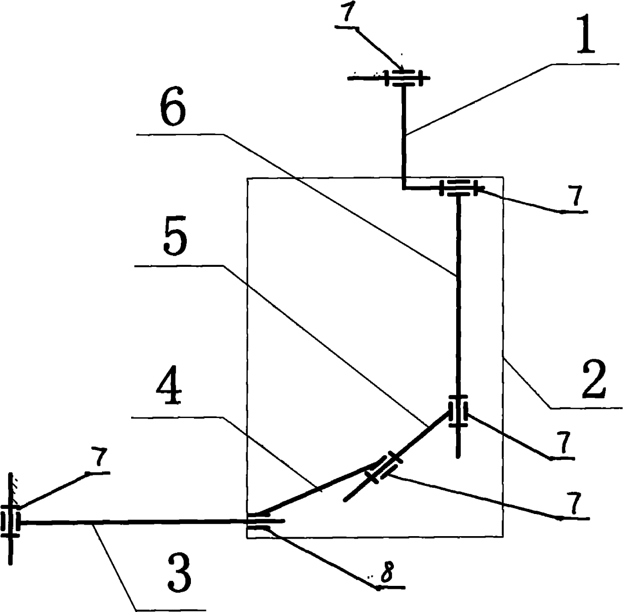
[0009] The main structure of the device in this embodiment includes a crank 1, a connecting rod 2, a rocker 3, a rotary motion pair 7, and a cylindrical surface motion pair 8. The kinematic pairs are connected; the upper member 6 forms a rotary motion pair structure with the crank 1 and the middle member 5 respectively, and the axes of the two rotary kinematic pairs intersect at an angle of 90°; the middle member 5 is connected to the lower member 6 and the upper member 4 respectively. A rotary kinematic pair structure is formed between them, and the axes of the two rotary kinematic pairs intersect to form an angle of 90°; a rotary kinematic pair structure is formed between the upper member 4 and the middle member 5, and a cylindrical kinematic pair structure is formed between the rocker 3, and the two The axes of kinematic pairs 7 and 8 intersect to form an angle of 90°; according to the arrangement of kinematic pairs, this device is a RRRRCR space crank-rocker device, wherein...


PUM


Abstract

The invention belongs to the technical field of mechanical transmission, and relates to a space crank rocker device capable of rotating directionally and freely in a three-dimensional space. The main body structure of the device comprises a crank, a connecting rod, a rocker, a gyration motion pair and a cylindrical surface motion pair, wherein the connecting rod is formed by connecting upper, middle and lower structural components through different motion pairs; the upper structural component forms a gyration motion pair structure respectively with the crank and the middle structural component, and the intersecting angle of the axes of the two gyration motion pairs is 90 DEG; the middle structural component forms a gyration motion pair structure respectively with the upper structural component and the lower structural component; the lower structural component forms a gyration motion pair structure with the middle structural component and forms a cylindrical motion pair structure with the rocker; and the utilized gyration motion pair has a rolling bearing structure, and the cylindrical motion pair has a straight line bearing structure. The device has the advantages of novel structure, simple principle, low manufacturing and processing cost, flexible azimuth adjustment and low energy consumption, can freely arrange the space positions of driving and driven shafts, and can be applied to power rotation and shake steering in three-dimensional space steering occasions of an electric fan, an air conditioner and the like.

Description

Technical field: [0001] The invention belongs to the technical field of mechanical transmission, and relates to a RRRRCR space crank and rocker mechanism capable of directional and arbitrary rotation in three-dimensional space, in particular to a space crank and rocker device. Background technique: [0002] Commonly used mechanisms for the motion transmission and conversion of space interlaced axes include cross belt transmission, space gear transmission, worm and worm gear transmission, cam transmission and space linkage mechanism, etc., which convert the rotational motion of the driving shaft into the reciprocating swing of the driven shaft. Compared with other mechanisms, the spatial link mechanism is connected in series with the planar link mechanism, and has low cost, simple structure, and low power consumption. At present, strict requirements are put forward for the space linkage mechanism. The links between the various components need rolling friction links, the space...

Claims


Application Information

Patent Timeline
Patent Type & Authority Applications(China)
IPC IPC(8): F16H21/46
Inventor 李淑玉王斌修
Owner QINGDAO TECHNOLOGICAL UNIVERSITY
Why Eureka
Try Eureka