
Method for generating high-precision stepping delay capable of dynamic calibration

A generation method and dynamic calibration technology, applied in the electronic field, can solve the problems of increasing system cost, increasing range, affecting accuracy, etc., and achieve the effect of expanding the delay output range

Inactive Publication Date: 2011-05-25
INST OF ELECTRONICS CHINESE ACAD OF SCI
View PDF0 Cites 36 Cited by
  • Summary
  • Abstract
  • Description
  • Claims
  • Application Information

AI Technical Summary

Problems solved by technology

The accuracy of the step delay directly affects the accuracy of the equivalent sampling, thus affecting the positioning and imaging accuracy of the radar working in the equivalent sampling mode
At present, there are many methods for generating step delay pulses. The method based on programmable delay chips usually increases the range by cascading, which increases the cost of the system, and lacks the calibration process of programmable delay chips.

Method used


Image

  • Method for generating high-precision stepping delay capable of dynamic calibration
  • Method for generating high-precision stepping delay capable of dynamic calibration
  • Method for generating high-precision stepping delay capable of dynamic calibration

Examples


Embodiment Construction

[0038] The method of the present invention will be described in detail below in conjunction with the accompanying drawings. It should be noted that the described embodiments are only intended to facilitate the understanding of the present invention, and have no limiting effect on it.

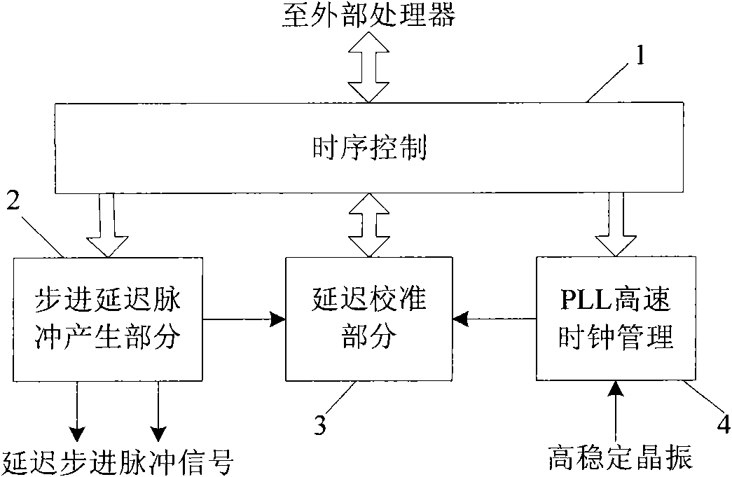
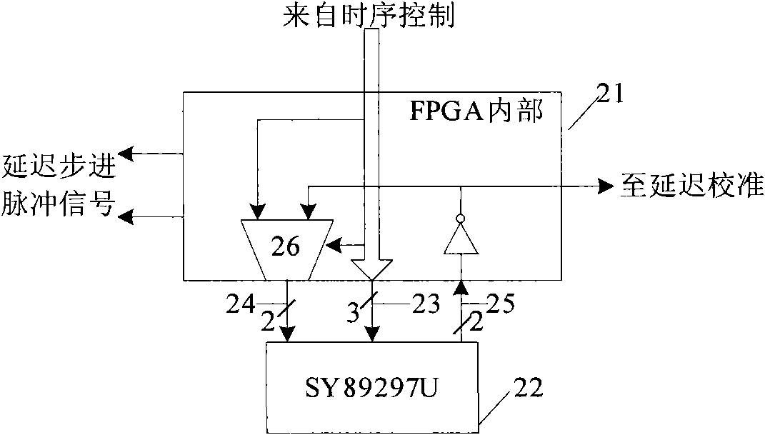
[0039] A dynamically calibrated high-precision step delay generation method of the present invention aims at the problems existing in the prior art, adopts a high-stability crystal oscillator and a PLL to generate a standard reference time base, and performs a step-by-step delay adjustment on a programmable delay chip Measurement and calibration; expand the delay range by organically combining the standard reference time base and the delay step of the programmable delay chip.

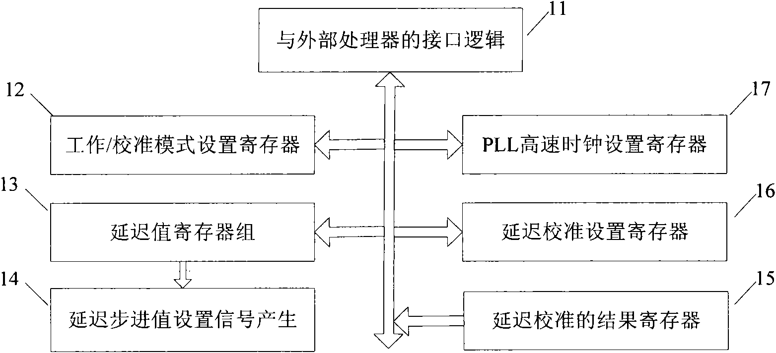
[0040] A dynamically calibrated high-precision step delay generation method of the present invention includes timing control, step pulse generation, PLL, and a delay calibration part, wherein:

[0041] The timing control ...


PUM


Abstract

The invention discloses a method for generating high-precision stepping delay capable of dynamic calibration, relating to an electronic technique. The method is realized based on a programmable delay chip, a high stability crystal oscillator and a field programmable gate array (FPGA) technology. In the method, a digital phase-lock technique is utilized to compare the delay value of the programmable delay chip with a high stability reference time base signal, so that the calibration for the delay value of the programmable delay chip can be realized. Because the stepping delay of the programmable delay chip and the total delay range are restricted mutually, the high stability crystal oscillator is combined with the programmable delay chip, thus realizing delay output with a wide range, small a stepping quantity and high precision. The method is used to provide launching and sampling timing sequences for equivalent sampling in radar signal acquisition, and has the advantages of wide usable range and high test precision.

Description

technical field [0001] The invention relates to the field of electronic technology, and is a dynamically calibrated high-precision step delay generation method, which can be used for high-speed equivalent sampling in radar signal detection, provides transmitter launch trigger and receiver receiving sampling timing signals, and improves the radar signal. measurement accuracy. Background technique [0002] Time-domain system signal sampling is divided into two mature methods: real-time sampling and equivalent sampling. Real-time sampling requires a digital-to-analog converter (ADC) whose digital-to-analog conversion time is less than the sampling period, which is limited by the speed bottleneck of the current ADC technology. In frequency radar signal detection, the real-time sampling mode is rarely used, but the sequential equal-length step equivalent sampling mode (hereinafter referred to as equivalent sampling) is often used. Equivalent sampling utilizes the periodicity or ...

Claims


Application Information

Patent Timeline
IPC IPC(8): G01S7/40G01S7/28
Inventor 孟升卫陈洁沈绍祥方广有
Owner INST OF ELECTRONICS CHINESE ACAD OF SCI
Learn More