Light guide plate and backlight module

A technology of backlight module and light guide plate, which is applied in the direction of optics, light guide, light source, etc., can solve the problems of reduced luminous efficiency, large color drift over time, accelerated aging, etc., and achieve the effect of improving light guide efficiency and avoiding the decline of light efficiency

Active Publication Date: 2011-05-25
SHENZHEN CHINA STAR OPTOELECTRONICS TECH CO LTD
View PDF5 Cites 35 Cited by
  • Summary
  • Abstract
  • Description
  • Claims
  • Application Information

AI Technical Summary

Benefits of technology

This technology solves problems when trying to improve how well an LCD panel looks because there are fewer fluorescence pigments than what was previously used for this purpose due to their ability to absorb more energy compared to other colors like red or green. By doing away with these materials, we aimed towards making better displays without decreasing brightness over time.

Problems solved by technology

This patented technical problem addressed in the present patents relates to improving the performance of LCD displays due to their ability to produce brighter colors without losing power when they are turned off. However, current methods involve adding extra components to improve these properties, which can increase manufacturing costs while reducing overall productivity.

Method used


Image

  • Light guide plate and backlight module
  • Light guide plate and backlight module
  • Light guide plate and backlight module

Examples


Embodiment Construction

[0033] In order to make the above-mentioned purposes, features and advantages of the present invention more obvious and understandable, the preferred embodiments of the present invention will be specifically cited below, together with the accompanying drawings, for a detailed description as follows:

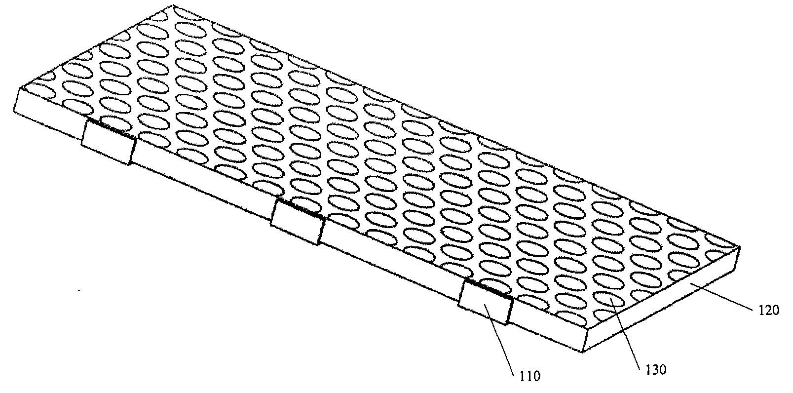
[0034] like Figure 4 Shown is a schematic diagram of the overall structure of the edge-lit backlight module in the present invention. The edge-lit backlight module includes several LEDs 210 and a light guide plate 220 . Wherein, the light guide plate 220 includes a bottom surface, a light incident surface and a light exit surface, the light exit surface is opposite to the bottom surface, and the bottom surface includes a plurality of dots 230 . Optionally, the light-emitting surface is connected to the light-incoming surface. The LED 210 is placed on the side of the light guide plate 220 , opposite to the light incident surface, and the light emitted by the LED 210 is incident...


PUM


Abstract

The invention provides a light guide plate and a backlight module. The light guide plate comprises a bottom surface, a light entering surface and a light emitting surface, wherein the light emitting surface is arranged opposite to the bottom surface; the bottom surface comprises a plurality of mesh points; the mesh points comprise fluorescent powder; and scattered particles are added selectively. Phenomena such as color offset caused by accelerated aging of the fluorescent powder which is close to a light-emitting diode (LED) chip and reduction in light emitting efficiency are avoided.

Description


Claims


Application Information

Patent Timeline
Owner SHENZHEN CHINA STAR OPTOELECTRONICS TECH CO LTD
Why Eureka
Try Eureka