Cavity filter and manufacturing method thereof, communication equipment and radio-frequency communication device

A cavity filter and radio frequency communication technology, which is applied in the field of communication, can solve the problems that screws affect the signal processing of the entire cavity filter, time-consuming assembly, high cost, and complicated process, and achieve low cost, good contact, and optimized communication The effect of indicators

Inactive Publication Date: 2011-05-25
ANHUI TATFOOK TECH CO LTD
View PDF6 Cites 12 Cited by
  • Summary
  • Abstract
  • Description
  • Claims
  • Application Information

AI Technical Summary

Problems solved by technology

[0006] During the research and practice of the prior art, the inventors of the present invention found that in the prior art, due to the use of screws to install the resonant rod, the

Method used


Image

  • Cavity filter and manufacturing method thereof, communication equipment and radio-frequency communication device
  • Cavity filter and manufacturing method thereof, communication equipment and radio-frequency communication device
  • Cavity filter and manufacturing method thereof, communication equipment and radio-frequency communication device

Examples


Example Embodiment

[0031] Example one

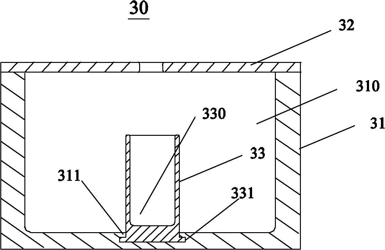
[0032] A cavity filter 30, such as image 3 As shown, the cavity filter 30 includes a cavity 31, a cover plate 32 and a resonance rod 33. The cover plate 32 covers the cavity 31 to form a resonant cavity 310. The resonance rod 33 is used as an insert and is formed by die-casting together with the cavity 31 or the cover plate 32, and the resonance rod 33 is located at the bottom of the cavity 31 and forms an integral structure with the cavity 31.

[0033] In this embodiment, the bottom of the resonant rod 33 is embedded in the cavity 31, that is, the resonant rod 33 is used as an insert to be integrated with the cavity 31 by die casting.

[0034] Specifically, the resonant rod 33 is first formed into an insert by stamping, die-casting or machining, and then the resonant rod 33 is used as an insert to die-cast with the cavity 31, so that the resonant rod 33 and the cavity 31 are tightly inlaid. Connected into a single structure.

[0035] It is easy for those skill...

Example Embodiment

[0038] Example two

[0039] A cavity filter 40, such as Figure 4 As shown, the cavity filter 40 includes a cavity 41, a cover plate 42 and a resonance rod 43. In this embodiment, the cavity filter 40 has the same general structure as that in the first embodiment, and the difference lies in the resonance. The die-cast joint between the rod and the cavity is provided with a groove 432 for limiting the resonance rod in the cavity. In order to facilitate the positioning of the resonance rod during the die casting process, the resonance rod 43 may penetrate the bottom of the cavity 41 and be flush with the bottom surface of the cavity 41.

[0040] Specifically, the concave portion of the cavity filter 40 further has a second flange 412, and the resonance rod 43 also has a groove 432 that matches the second flange 412. In this way, the resonance rod 43 is connected to the first flange through the protrusion 431. The fitting of the flange 411 and the fitting of the groove 432 and the se...

Example Embodiment

[0041] Example three

[0042] A cavity filter 50, such as Figure 5 As shown, the cavity filter 50 includes a cavity 51, a cover plate 52 and a resonance rod 53. The cover plate 52 covers the cavity 51 to form a resonant cavity 510. The resonant rod 53 is die-cast in the resonant cavity 510 as an insert, and the resonant rod 53 is located at the bottom of the cavity 51 and forms an integral structure with the cavity 51.

[0043] In this embodiment, the resonant rod 53 and the cavity 51 can be made of different materials. For example, the resonant rod 53 can be made of copper or iron, and the cavity 51 can be made of aluminum alloy and other materials, depending on the material's signal conduction characteristics and mechanical strength. As well as material costs, etc. to choose.

[0044] In a preferred embodiment, the thickness of the resonant rod 53 is smaller than the thickness of the cover 52 and the cavity 51. The resonant rod 53 can be stamped and formed from a thin plate. The...


PUM


Abstract

The embodiment of the invention provides a cavity filter and a manufacturing method thereof. The cavity filter comprises a cavity, a cover plate and a resonance rod, wherein the cover plate seals the cavity; the resonance rod serving as an insert is cast together with the cavity or the cover plate without installing screws, so the cavity filter is efficient and time-saving and has low cost; and the resonance rod is well contacted with the cavity or the cover plate, so the communication index of the cavity filter is greatly optimized. Because the resonance rod is in an insert module form, the resonance rod and the cavity can be made of different materials, and the materials can be selected according to the signal transduction property, mechanical strength, cost and the like of the materials.

Description

【Technical field】 [0001] The invention relates to filter technology in the communication field, in particular to a cavity filter and a manufacturing method thereof, a radio frequency communication device and communication equipment. 【Background technique】 [0002] As a frequency selective device, cavity filters are widely used in the field of communication, especially in the field of radio frequency communication. In the base station, the filter is used to select the communication signal and filter out the clutter or interference signal outside the frequency of the communication signal. [0003] Cavity filters generally include three types, the first type is coaxial cavity filter, the second type is dielectric filter, and the third type is waveguide filter. [0004] As far as the coaxial cavity filter (hereinafter referred to as the cavity filter) is concerned, please refer to figure 1 and figure 2 ,in, figure 1 A schematic cross-sectional view of a cavity filter and it...

Claims


Application Information

Patent Timeline
IPC IPC(8): H01P1/202H01P11/00
Inventor 孙尚传童恩东
Owner ANHUI TATFOOK TECH CO LTD
Why Eureka
Try Eureka