
Stator core for an electric machine

A technology of stator core and generator, applied in the field of stator core

Inactive Publication Date: 2011-05-25
ROBERT BOSCH GMBH
View PDF1 Cites 6 Cited by
  • Summary
  • Abstract
  • Description
  • Claims
  • Application Information

AI Technical Summary

Problems solved by technology

Said publication is silent on the stamping method used, and likewise does not describe the relationship between the amount of scrap produced during stamping and the initial strip quantity or the remaining pole cross-section.

Method used


Image

  • Stator core for an electric machine
  • Stator core for an electric machine
  • Stator core for an electric machine

Examples


Embodiment Construction

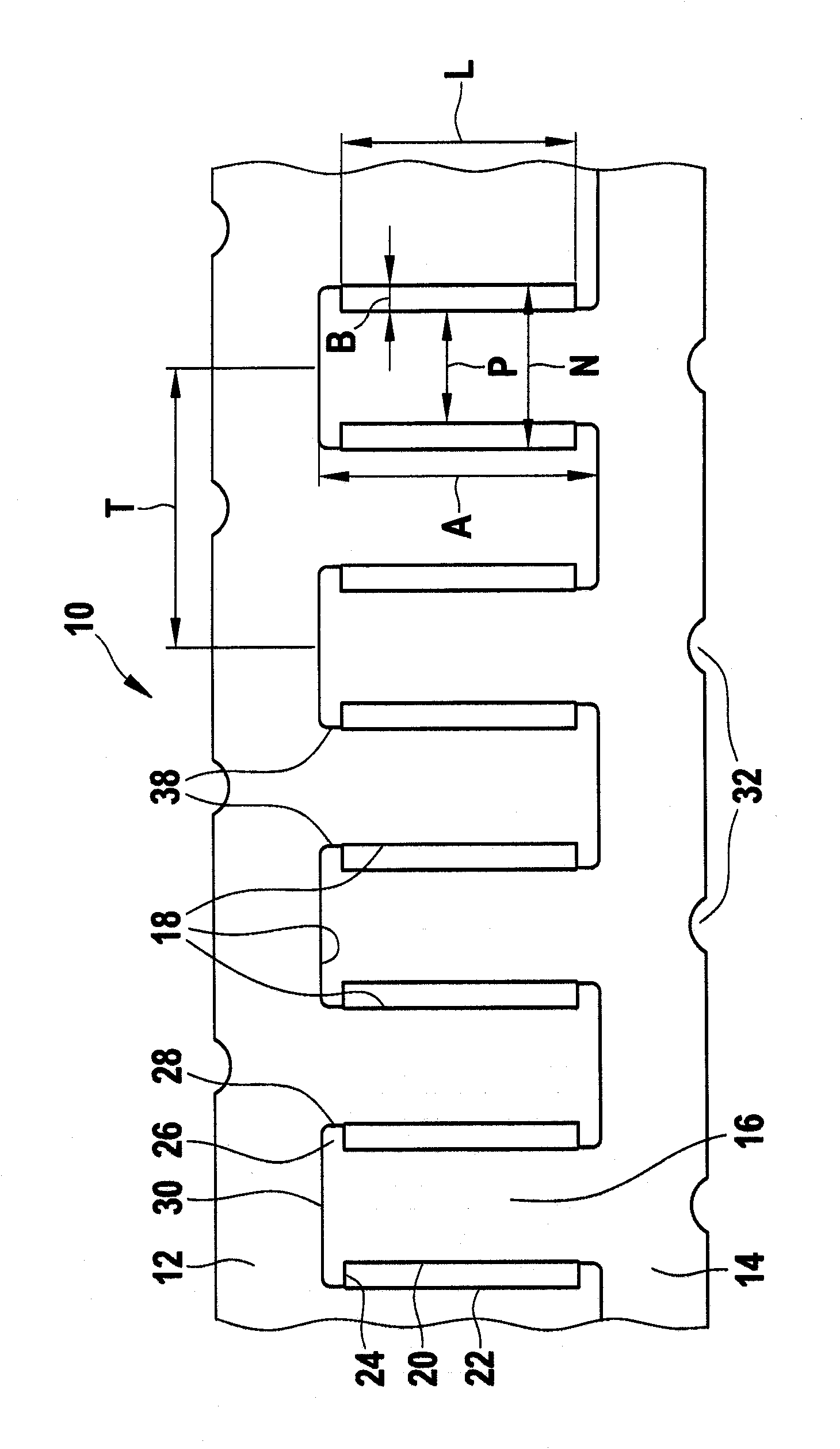
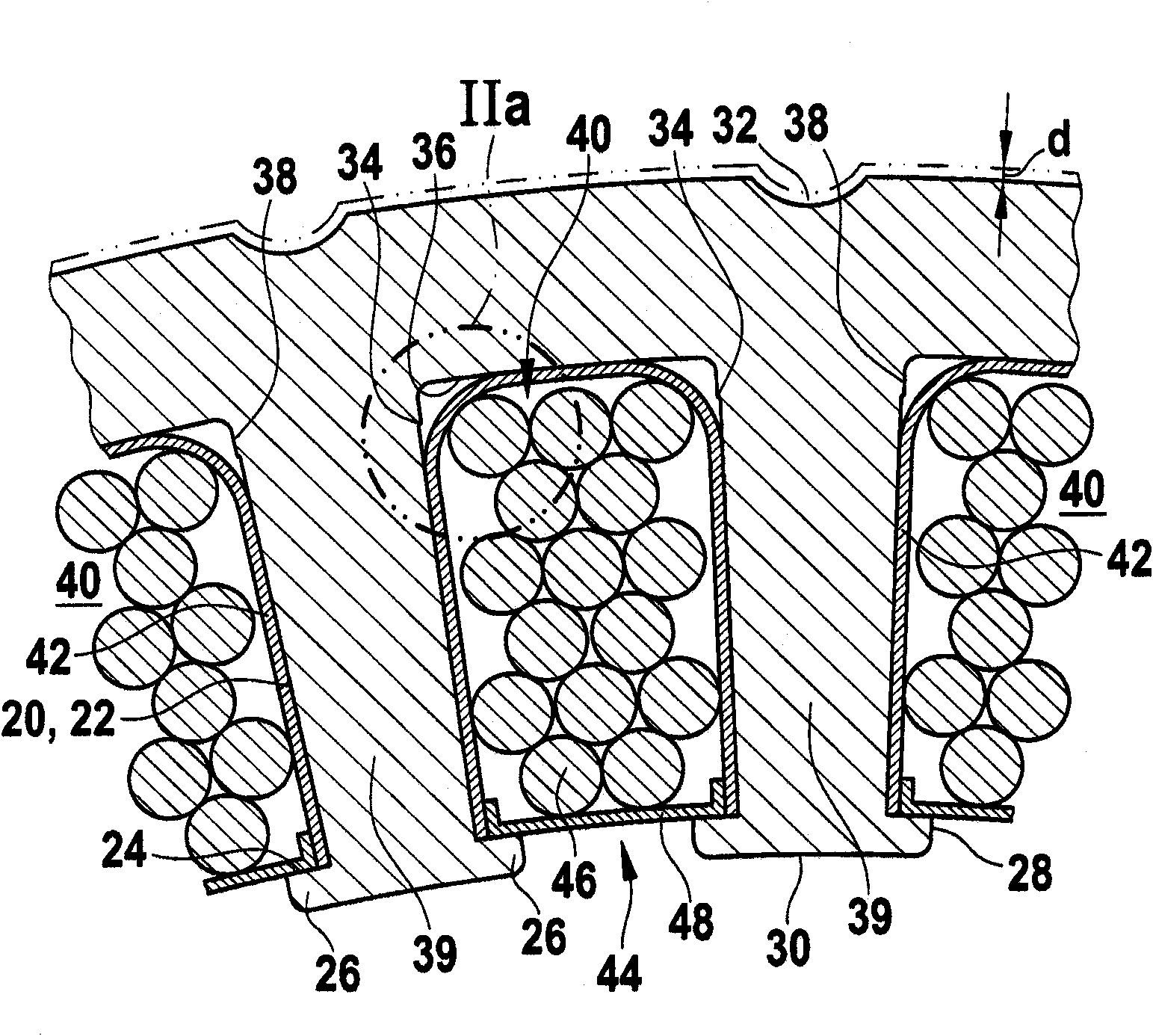
[0013] exist figure 1 10 denotes a strip made of electrical steel sheet which is partly stamped and partly cut into two intermeshing individual strips 12 and 14 . The strip 10 consists of a soft-magnetic electrical steel sheet suitable for the production of stator cores, such as is defined, for example, in DIN 46400 and is known in principle. The important principles of this steel sheet are the coercive magnetic field strength below 1000A / m, suitable alloy additions (especially Si, Ni, Co, Mo and other alloy additions) and special treatment processes such as hot rolling or cold rolling rolling, thereby obtaining advantageous soft magnetic properties on the one hand and favorable processing conditions on the other hand.

[0014] Through the separation process of the strip 10 , mirror-image individual strips engaging with each other are produced as lamellae 12 and 14 , which have pole-shaped elevations 16 and groove-shaped recesses 18 . In this case, the separation is carried ...


PUM

PropertyMeasurementUnit
Thicknessaaaaaaaaaa

Abstract

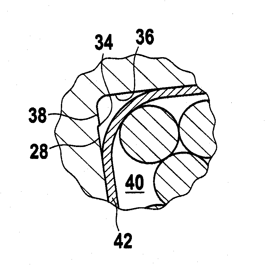
The invention relates to a stator core for an electric machine, in particular for the generator of a motor vehicle. Said stator core is laminated or wound from segments (12, 14) that are punched and / or cut out in a tooth-forming manner from a preferably strip-shaped magnetic steel sheet (10) and form a plurality of notches (40) and teeth (39). The region of the tooth flank (20) and the notch flank (22) is punched in such a way that the tooth width (P) and the notch width (N) are substantially constant in the unbent segments (12, 14) along the entire length (A) of the teeth. The ratio (alpha) between the tooth width (P) and the notch pitch (T) is greater than 0.38 and smaller than 0.5, thus minimizing magnetic resistance and limiting the amount of scrap to a level lying within the geometrical and production-related possibilities.

Description

technical field [0001] The invention relates to a stator core for an electric machine. Background technique [0002] The invention relates to a stator core for an electric machine, such as is known from US-PS 3577851. The stator core disclosed in this publication is formed helically by the winding method, is punched out from two identical strips of strip-shaped electrical steel sheet in a toothed manner and is each wound separately. into a stator core. The two strips each have recesses and finger-shaped projections which form the teeth and grooves of the stator core after the strips have been rolled up. Said publication is silent on the punching method used, and likewise does not say anything about the relationship between the quantity of scrap produced during punching and the initial strip quantity or the remaining pole cross-section. Contents of the invention [0003] Compared to this, the stator core according to the invention having the features of the independent c...

Claims


Application Information

Patent Timeline
IPC IPC(8): H02K15/02H02K1/16
CPCH02K15/026H02K1/165
Inventor D・阿玛拉尔
Owner ROBERT BOSCH GMBH
Learn More