Lubrication structure of active valve mechanism

A lubricating structure and moving valve technology, applied in the lubrication of valve accessories, etc., can solve problems such as increased capacity, achieve the effects of reduced oil capacity and shortened oil return time

Active Publication Date: 2011-06-01
HONDA MOTOR CO LTD
View PDF7 Cites 4 Cited by
  • Summary
  • Abstract
  • Description
  • Claims
  • Application Information

AI Technical Summary

Problems solved by technology

[0004] However, in the case of using the V-shaped rib disclosed in Patent Document 1, since the V-shaped rib is not connected to other ribs, the oil overflowing from the V-shaped groove remains attached to the cover member until the oil reaches the V-shaped rib. The oil return passage takes time, and there is a problem that the required capacity increases

Method used


Image

  • Lubrication structure of active valve mechanism
  • Lubrication structure of active valve mechanism
  • Lubrication structure of active valve mechanism

Examples


Embodiment Construction

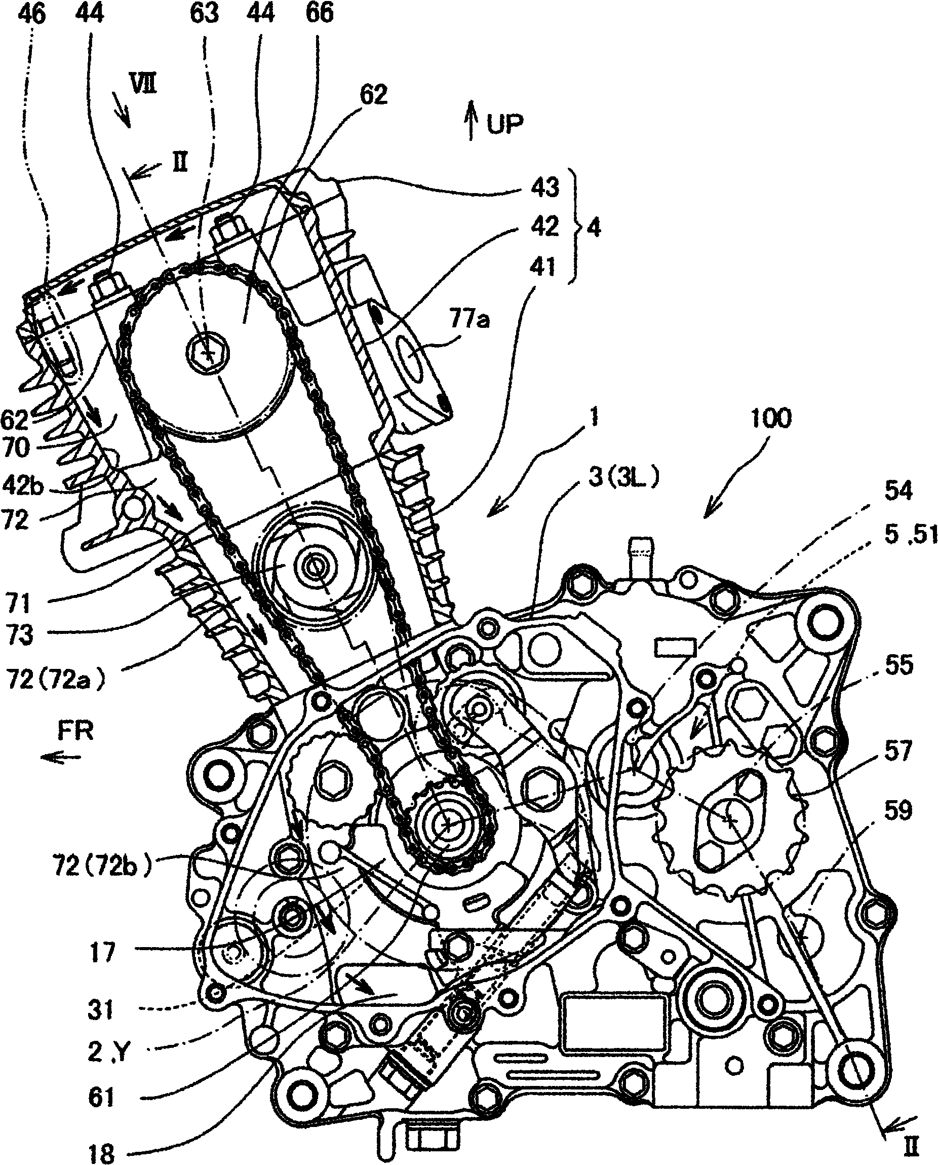
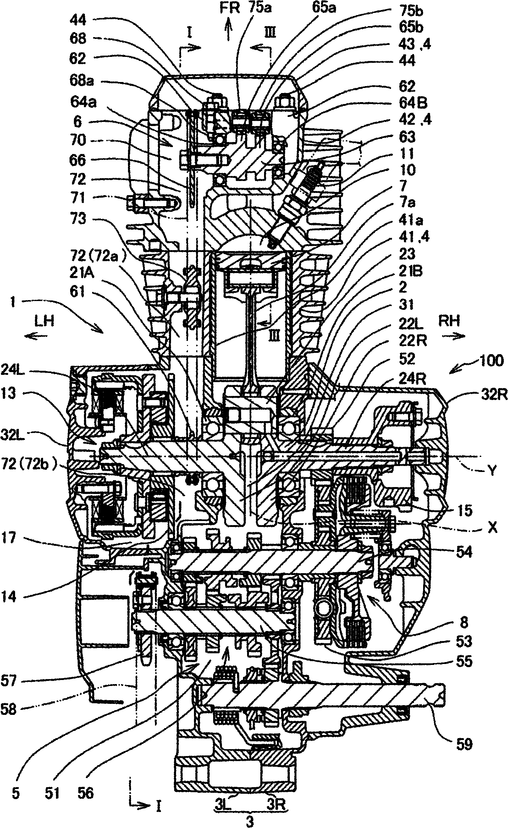
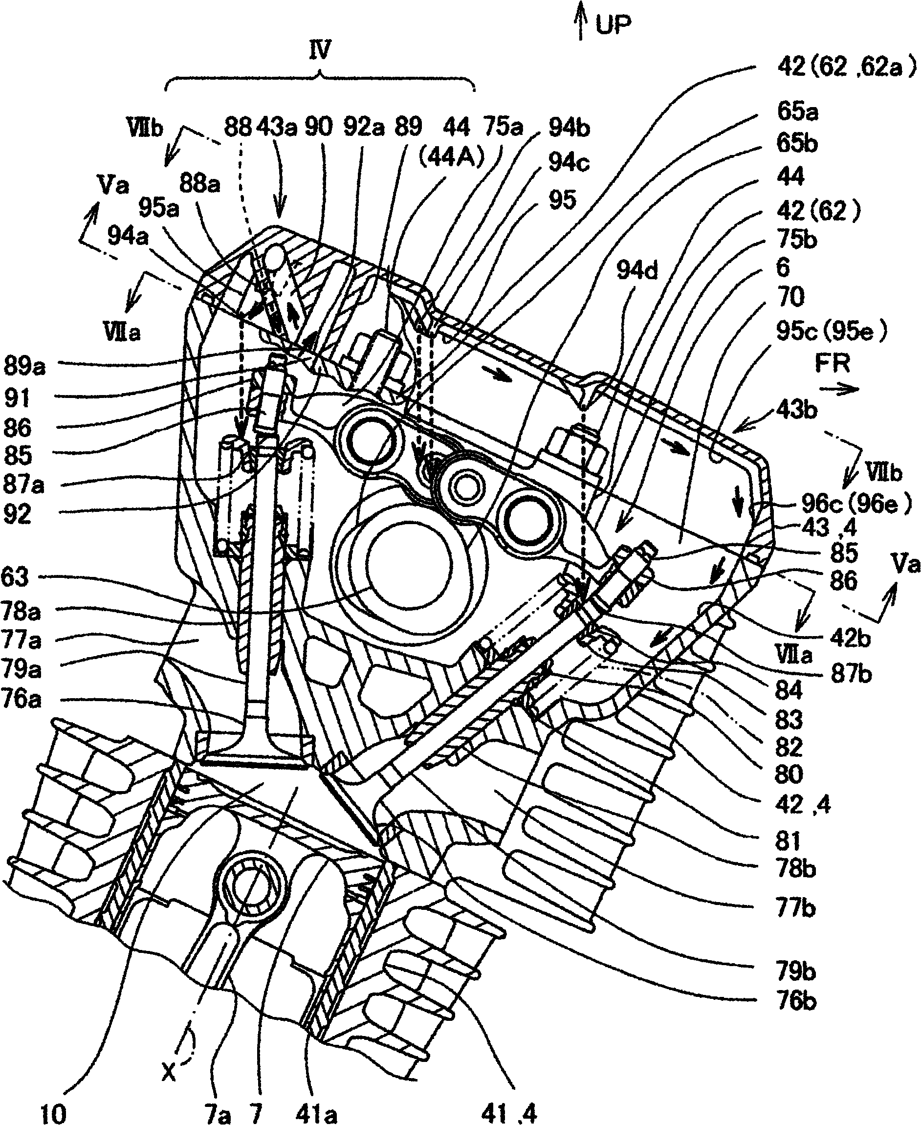
[0037] according to Figure 1 to Figure 11 , the lubricating structure of the movable valve mechanism of the internal combustion engine according to the first and second embodiments of the present invention, and the lubricating structure of the movable valve mechanism of other embodiments related to the present invention studied by the present inventors will be described.

[0038] Small arrows attached to devices and structural parts in each figure schematically indicate the flow of lubricating oil.

[0039] In addition, directions such as front, rear, left, right, up and down in this specification correspond to the direction of the vehicle in a state where the internal combustion engine of each embodiment is mounted on a vehicle such as a motorcycle.

[0040] In the drawings, an arrow FR indicates the front of the vehicle, an arrow LH indicates the left side of the vehicle, an arrow RH indicates the right side of the vehicle, and an arrow UP indicates the upper side of the ve...


PUM


Abstract

The invention provides a lubrication structure of an active valve mechanism capable of satisfactorily lubricating the active valve mechanism and further shortening the time of oil returning to an oil return path.Meanwhile, the required oil capacity is also reduced.An internal combustion engine (1) with a lubrication structure of the active valve mechanism comprises a cylinder body (41), an active valve chamber (70) and an oil return chamber (72).The cylinder body (41) extends upwards from the crankcase (3) of the internal combustion engine (1) and extends forwards with respect to the plumb direction.The active valve chamber (70) is formed by a cylinder head (42) and a cylinder head cover (43) arranged above the cylinder body.The oil return chamber (72) is equipped with a space communicating with the active valve chamber, the cylinder body and the crankcase.The inner surface of the cylinder head cover, that is the up and down opposite position of the valve stem ends (87a, 87b) or the cams (65a, a65b) of the active valve mechanism, is equipped with an oil dropping part (94a - 94d) and guide ribs (95b, 95c).The guide ribs (95b, 95c) connected with the oil dropping part extends downwards from the oil dropping part and toward the oil return chamber.

Description

technical field [0001] The present invention relates to a lubricating structure of a movable valve mechanism installed in an internal combustion engine of a vehicle, and particularly relates to a lubricating structure of a movable valve mechanism capable of achieving good lubrication and reducing the required oil capacity. Background technique [0002] As the lubricating structure of the movable valve mechanism, the following structure is disclosed in the following patent document 1: on the inner surface of the cover member that blocks the opening for adjusting the tappet gap provided in the cylinder head, a V-shaped lubricating oil for collecting lubricating oil is provided. The rib drips the oil trapped in the V-shaped groove onto the stem end. [0003] Patent Document 1: (Japanese) Unexamined Patent Publication No. 2006-283623 ( Figure 8 , Figure 9 ) [0004] However, in the case of using the V-shaped rib disclosed in Patent Document 1, since the V-shaped rib is not c...

Claims


Application Information

Patent Timeline
Patent Type & Authority Applications(China)
IPC IPC(8): F01M9/10
Inventor 久我信二坂本雅美
Owner HONDA MOTOR CO LTD
Why Eureka
Try Eureka