
Countercurrent cooler

A counter-current cooling and shell technology, applied in heat exchanger types, direct contact heat exchangers, lighting and heating equipment, etc., can solve problems such as poor cooling uniformity, uneven airflow, and material accumulation, and achieve reliability High, uniform flow field distribution, good transmission rigidity

Inactive Publication Date: 2011-06-01
扬州华美知识产权事务有限公司
View PDF4 Cites 15 Cited by
  • Summary
  • Abstract
  • Description
  • Claims
  • Application Information

AI Technical Summary

Problems solved by technology

The existing countercurrent cooling equipment for granular materials mainly has the following disadvantages: (1) The transmission mechanism for spreading materials is complicated, and it is easy to cause failures such as chain drop and vibration; The difference in the airflow passing through the material will eventually lead to poor cooling uniformity; (3) The inclined throwing plate occupies too much cooling chamber space 9, about 50%, which reduces the effective cooling height, thereby affecting the output of the cooler; (4) The fully open air path structure with offset outlets leads to extremely uneven airflow and affects cooling uniformity; (5) The adjustment fence is made up of a group of flat iron-shaped grid bars with tailor-welded combination, the structure and connection method are unreasonable, and the process Poor performance, serious welding deformation, difficult to meet the bottom flatness requirements, causing a large amount of material accumulation

Method used


Image

  • Countercurrent cooler
  • Countercurrent cooler
  • Countercurrent cooler

Examples


Embodiment Construction

[0018] Below in conjunction with accompanying drawing, the present invention is further explained:

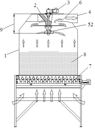
[0019] Such as figure 1 As shown, the counterflow cooler includes a circular shell 1 with an inner chamber, a feed port 2, a motor 3 and a discharge structure 7; the feed port 2 is arranged on the upper part of the shell 1, preferably at the top; the air suction port 4 can be It is arranged on the side of the upper part of the casing 1; the motor 3 can be arranged on the casing 1, or it can be separated from the casing 1 in a split manner, and the discharge mechanism 7 is arranged at the bottom of the casing 1.

[0020] A feed pipe 11 is provided in the housing 1 to communicate with the feed port 2, a rotating shaft 34 is provided in the feeding pipe 11 to connect with the motor 3, and a material uniform distribution mechanism 5 is provided at the bottom of the rotating shaft 34.

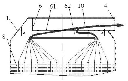
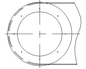
[0021] Such as figure 2 with image 3 As shown, the air duct 6 is arranged in the housing 1,...


PUM


Abstract

The invention discloses a countercurrent cooler comprising a casing with an inner cabin. A feeding hole and an air suction inlet are arranged on the casing, and a discharging mechanism is arranged at the bottom of the casing; the casing is internally provided with an air duct communicated with the air suction inlet, a channel communicated with the inner cabin of the casing is arranged on the air duct, and an air deflector is arranged below the channel; a feeding pipe extending from the feeding hole enters the inner cabin of the casing via the channel, a throwing plate is arranged below an exit of the feeding pipe and fixed on a rotating shaft, and the rotating shaft is driven by a motor in a direct-coupling mode. Due to the adoption of a unique air duct design, the direct-coupling mode for driving the rotating shaft by the motor, a particular throwing plate design and a regulating fence with an overall stamping structure, the space is saved by 30%, the equipment yield is effectively increased, and thus the countercurrent cooler disclosed by the invention is a novel countercurrent cooler which has the advantages of high yield, good cooling uniformity, high reliability in a transmission mechanism, no deposition in the discharging mechanism and the like.

Description

technical field [0001] The invention relates to a countercurrent cooler, in particular to a countercurrent cooler for cooling granular materials such as feed. Background technique [0002] Existing countercurrent cooling equipment for pellets, such as Figure 9 As shown, its structure and working principle are as follows: the material 12 enters the cooler through the material guide pipe, falls on the inclined throwing plate along the tapered bucket, and slides along the throwing plate to the cooler chamber; The plate has a set of driving mechanism to drive the rotation so that the material can be spread around the cooler. There is an air suction port on the side of the cooler connected to the inlet of the fan. When the fan is working, a negative pressure is formed in the cavity above the cooler. Take away the heat and moisture in the material to achieve the purpose of cooling. When the material accumulates to the specified height, the discharge mechanism reciprocates under...

Claims


Application Information

Patent Timeline
IPC IPC(8): F28C3/12
Inventor 闾宏张文良倪永东
Owner 扬州华美知识产权事务有限公司
Learn More