Radiating fin and heat exchanger

A technology of heat exchangers and heat sinks, which is applied in heat exchange equipment, lighting and heating equipment, laminated components, etc., can solve the problems of low heat dissipation efficiency of heat sinks, improve heat dissipation performance, increase heat dissipation efficiency, and facilitate processing Effect

Inactive Publication Date: 2011-06-01
HAIER GRP CORP +1
View PDF0 Cites 2 Cited by
  • Summary
  • Abstract
  • Description
  • Claims
  • Application Information

AI Technical Summary

Problems solved by technology

[0008] The present invention solves the problems of heat dissipation and low efficiency of heat sinks in the prior art, and provides a heat sink and a heat exchanger, which can effectively solve the problem of heat dissipation of heat sinks and improve heat dissipation efficiency

Method used


Image

  • Radiating fin and heat exchanger
  • Radiating fin and heat exchanger

Examples


Embodiment Construction

[0028] The present invention will be further described below in conjunction with the accompanying drawings.

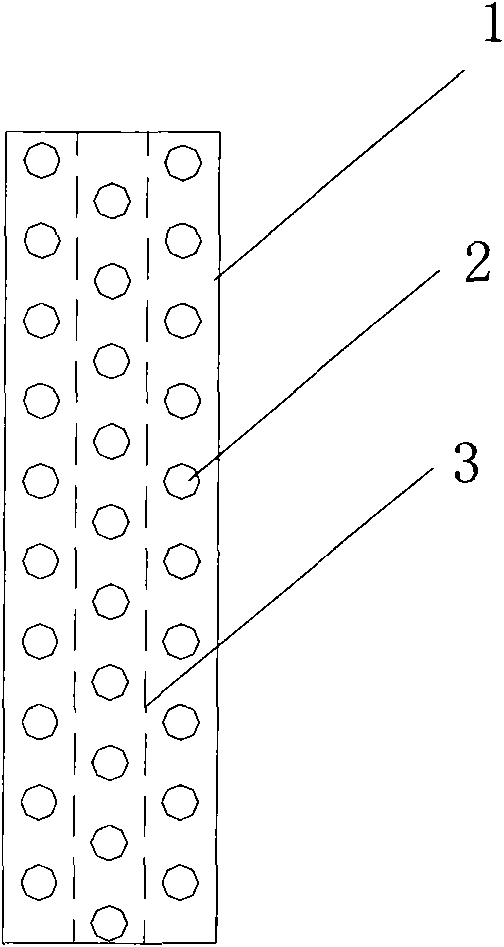
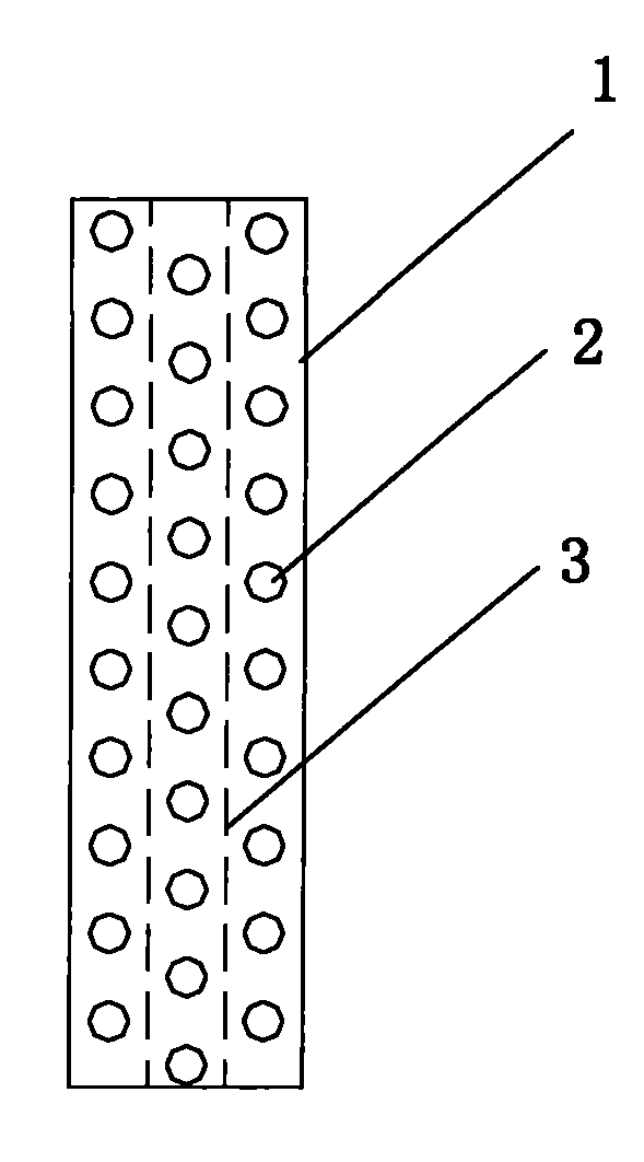
[0029] see figure 1 , an embodiment of a heat sink in the present invention, 3 rows of hairpin jacks 2 are arranged on the heat sink 1, and a penetrating heat dissipation is provided in the middle of the positions between the hairpin jacks 2 of adjacent rows of the heat sink 1. The slits 3 of the sheet form part of the connection structure. There are two slits 3, and each slit 3 is intermittently arranged along a straight line to form multiple slits, and the length of each slit is greater than the aperture of the hairpin tube jack 2.

[0030] A heat exchanger according to the present invention includes cooling fins 3 and hairpin tubes. At least two rows of hairpin tube sockets are arranged on the heat sink 3 . There is refrigerant in the hairpin tubes, and the hairpin tubes penetrate into the hairpin tube sockets. The heat sink 3 structure adopted is the heat sink 3 ...


PUM


Abstract

The invention provides a radiating fin, wherein at least two rows of hairpin tube jacks are arranged on the radiating fin; a lancing passing through the radiating fin, is arranged between the adjacent rows of hairpin tube jacks, so as to form a partial connection structure; the lancing is arranged right between two rows of hairpin tube jacks; and the invention also provides a heat exchanger having the radiating fin, which can solve the heat transfer problem of the radiating fin effectively and increase the radiating efficiency.

Description

technical field [0001] The invention belongs to the technical field of heat exchanger manufacturing, and mainly relates to the improvement of the heat sink structure of the heat exchanger of an air-conditioning and heating system, in particular to a heat sink and a heat exchanger. Background technique [0002] At present, the heat exchanger of the air-conditioning and heating system is that multiple rows of hairpin tubes are inserted on a large heat sink, and the reverse heat transfer performance is the best for heating. Its characteristics are: the temperature of the refrigerant in the back is high, and the temperature of the refrigerant in the front is low. But in a system there will be the following situations: [0003] 1. The temperature difference between the front and rear refrigerants is small, and the front and rear refrigerants dissipate heat respectively. do not affect each other. The heat sink is less efficient in the rear. Affect heat sink heat dissipation. ...

Claims


Application Information

Patent Timeline
Patent Type & Authority Applications(China)
IPC IPC(8): F28F3/00
Inventor 周小光
Owner HAIER GRP CORP
Why Eureka
Try Eureka