Onsite splicing and mounting method for extra-large and overweight box crane girders

An installation method and crane beam technology, which are applied in the field of steel structure construction, can solve the problems of inconvenient installation methods of extra-large crane beams, and achieve the effects of saving auxiliary materials and flaw detection costs, high visual quality, and light hoisting.

Active Publication Date: 2011-06-08
MCC5 GROUP CORP SHANGHAI
View PDF1 Cites 28 Cited by
  • Summary
  • Abstract
  • Description
  • Claims
  • Application Information

AI Technical Summary

Problems solved by technology

[0004] Therefore there is above-mentioned inconvenience and problem in the installation method of known extra-large crane girder

Method used


Image

  • Onsite splicing and mounting method for extra-large and overweight box crane girders
  • Onsite splicing and mounting method for extra-large and overweight box crane girders
  • Onsite splicing and mounting method for extra-large and overweight box crane girders

Examples


Embodiment

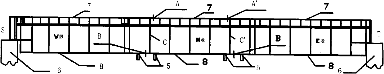
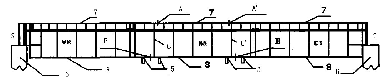
[0027] The 4300mm wide and thick plate project of Laiwu Iron and Steel Co., Ltd. in Shandong Province was designed by Shandong Metallurgical Design Institute and was contracted by MCC Chenggong Shanghai Fifth Metallurgy. In the history of metallurgical construction, super-long and super-heavy box crane girders are rare, realizing the idea of ​​replacing double I-beams with box crane girders with super large column spacing in industrial plants. According to road traffic restrictions, limited by the equipment conditions of the construction site and nearby processing plants, and there is no means of transportation for a single 320-ton 54-meter-long component, the long-span box crane girder can only be manufactured by the factory, segmented, and assembled on site scheme.

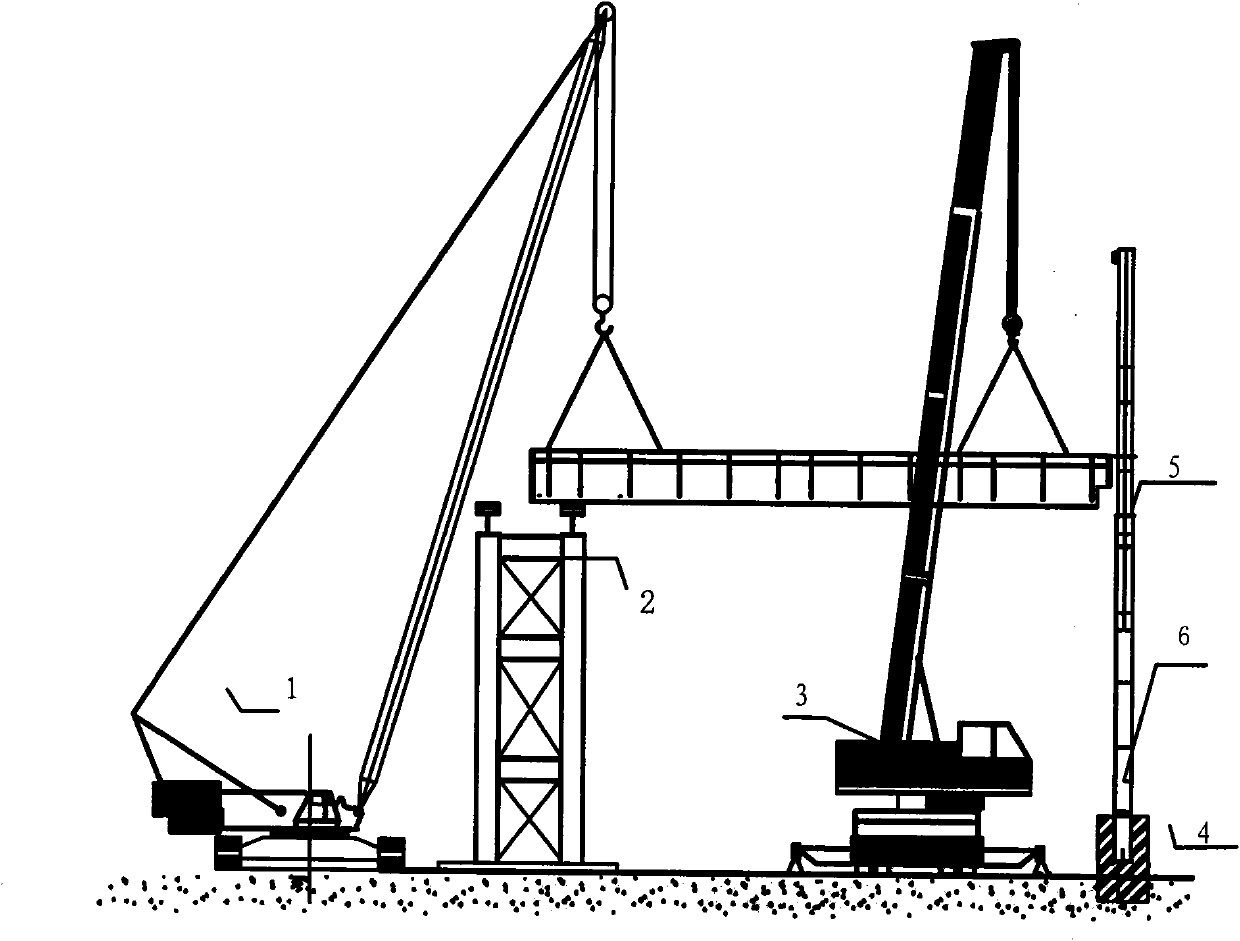
[0028] see now figure 1 and figure 2 , figure 1 It is a segmental schematic diagram of an oversized and overweight box-type crane girder according to an embodiment of the present invention, figure 2 It is ...


PUM


Abstract

The invention discloses an onsite splicing and mounting method for an extra-large and overweight box crane girder. The box crane girder consists of three sections, namely a W section, an M section and an E section, wherein the three sections of girders are connected on two steel columns; and the onsite splicing and mounting method for the crane girder is characterized by comprising the following steps of: 1, respectively assembling the three sections of the girders in a factory before the box crane girder enters the site, arranging two brackets at positions of splicing interfaces of the three sections on the box crane girder according to the lengths of the three sections between the two steel columns, arranging a lifting jack on a platform of the brackets, and measuring positioning lines on crossbeams of the brackets; and 2, splicing and mounting the box crane girder on site and at high altitude, namely manufacturing the extra-large and overweight box girder into the three sections of the girders in the factory, introducing the sections into the site according to a lifting sequence of the W section, the M section and the E section, directly lifting the sections by employing a 120t crawler crane and a 260t truck crane, lifting to right places by sections, splicing and welding, and unloading and detaching the brackets after the box crane girder passes the welding construction defect detection.

Description

technical field [0001] The invention relates to a steel structure construction method, in particular to an on-site splicing and installation method of super-large and super-heavy box-type crane girders. Background technique [0002] Existing super-long traveling girders of the same type usually adopt a double I-beam structure. Compared with box girders, to achieve the same structural mechanical properties, the plates used are thicker, which increases the weight, increases the difficulty of welding, and increases the cost of transportation and hoisting. [0003] Chinese Patent No. 200810079301.2 discloses an installation method of a super-large crane girder. The crane beam structure is divided into three sections: left, middle and right. First, a temporary support is erected on the ground at the 1 / 3 column spacing of the crane girder installation site. There is a jack on the platform to adjust the levelness and camber of the butt joint of the crane girder in a small amount. ...

Claims


Application Information

Patent Timeline
Patent Type & Authority Applications(China)
IPC IPC(8): B66C13/04B66C13/08
Inventor 程先云刘大恩刘作安舒峥理陈瑜建单伟林刘九朝
Owner MCC5 GROUP CORP SHANGHAI
Why Eureka
Try Eureka