Discharge ionization current detector

A technology of ionization current and current detection unit, applied in instruments, measuring devices, scientific instruments, etc., can solve the problems of high device price and high power supply price, and achieve the effect of low cost

Inactive Publication Date: 2011-06-08
OSAKA UNIV +1
View PDF6 Cites 15 Cited by
  • Summary
  • Abstract
  • Description
  • Claims
  • Application Information

AI Technical Summary

Problems solved by technology

Therefore, there is a problem that the price of the required power suppl

Method used


Image

  • Discharge ionization current detector
  • Discharge ionization current detector
  • Discharge ionization current detector

Examples


Embodiment Construction

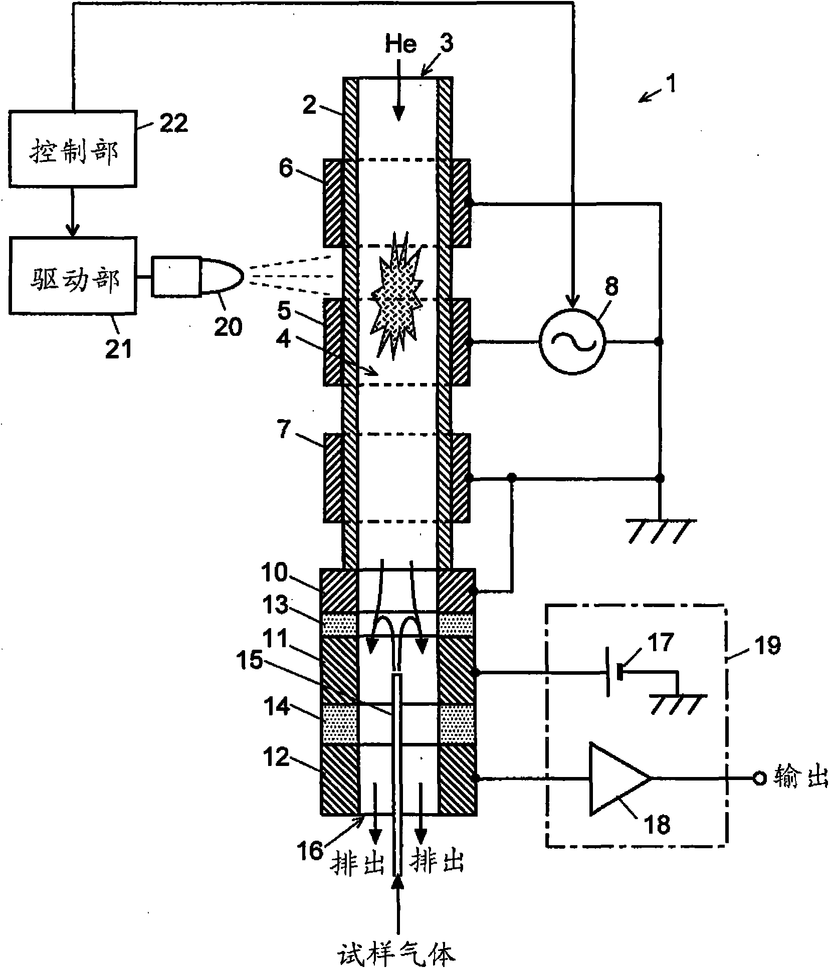
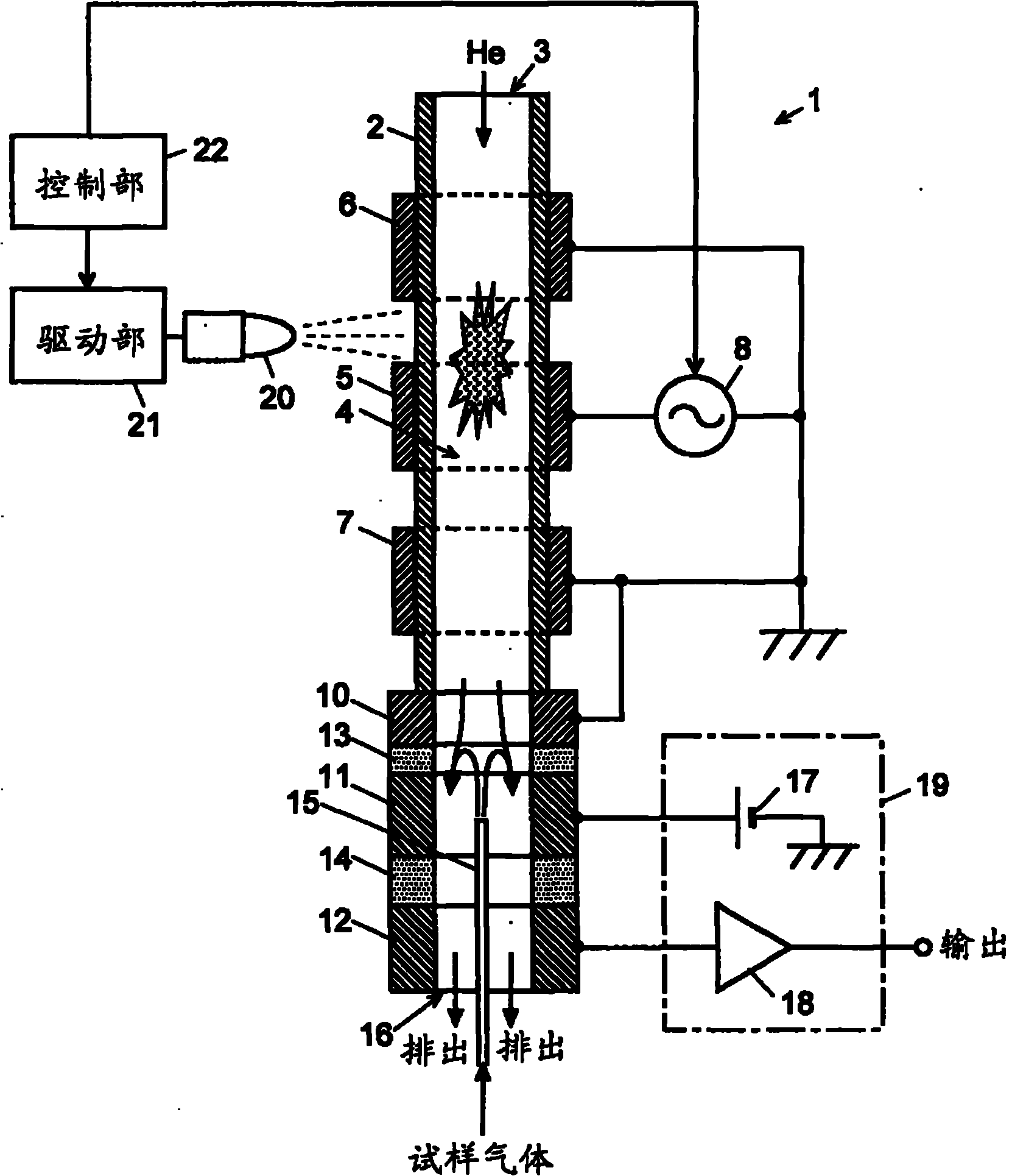
[0029] Next, a discharge ionization current detector according to an embodiment of the present invention will be described with reference to the drawings. figure 1 It is a schematic configuration diagram of the discharge ionization current detector of this embodiment.

[0030] The discharge ionization current detector 1 of the present embodiment includes a cylindrical tube 2 made of a light-transmitting dielectric such as quartz, and a gas flow path 4 is formed therein. As the cylindrical tube 2, for example, a quartz tube having an outer diameter of Φ3.9 mm can be used. Ring-shaped plasma generation electrodes 5 , 6 , and 7 made of metal (for example, SUS, copper, etc.) are provided around the outer wall surface of the cylindrical tube 2 at predetermined distances from each other. Since the wall surface of the cylindrical tube 2 exists between the electrodes 5, 6, 7 for plasma generation and the gas flow path 4, the wall itself as a dielectric acts as a dielectric covering ...


PUM


Abstract

Provided is a discharge ionization current detector. To reduce the cost of a high-voltage power supply unit by reducing the discharge starting voltage for a low-frequency dielectric barrier discharge. Light from light source unit (20) located externally to cylindrical tube (2) through which a plasma gas (He) flows is irradiated through the wall surface of the cylindrical tube (2) onto a plasma generation region (the region between plasma generation electrodes (6 and 7) located in gas flow path (4). The light energy excites the He molecules or the minute quantities of impurity gas molecules present in the He gas, causing photo-ionization. This causes a discharge to start, and a plasma to be formed, when a low-frequency voltage of a voltage that is less than the usual discharge starting voltage is applied across electrode (5) and electrodes (6, 7). Once the discharge starts, the discharge is sustained when the usual discharge sustaining voltage is applied across electrode (5) and electrodes (6, 7). This means that the light source unit (20) has to be on only for a short duration when discharging is started.

Description

technical field [0001] The present invention mainly relates to a discharge ionization current detector suitable as a detector for a gas chromatograph (GC: gaschromatograph), and more specifically, to a discharge ionization current detector using a low-frequency barrier discharge. Background technique [0002] As detectors used in GC, thermal conductivity detectors (TCD), electron capture detectors (ECD), hydrogen flame ionization detectors (FID), flame photometric detectors (FPD), and flame thermionic detectors have been practically used in the past. detectors (FTD) and other types of detectors. Most commonly among such detectors, FIDs are used especially for the detection of organics. The FID uses a hydrogen flame to ionize the sample components in the sample gas and measures the ion current, realizing a large dynamic range of about 6 bits. However, FID has the following disadvantages: (1) Due to the low ionization efficiency, a sufficiently low minimum detection amount c...

Claims


Application Information

Patent Timeline
IPC IPC(8): G01N30/64
CPCG01N2030/642G01N30/64
Inventor 品田惠北野胜久
Owner OSAKA UNIV
Why Eureka
Try Eureka