
Intersection situation recognition system

A technology of intersections and conditions, applied in traffic control systems, collision avoidance systems, traffic control systems for road vehicles, etc., to solve problems such as difficult to see, difficult to see positions for cars, and inability to confirm road conditions.

Inactive Publication Date: 2011-06-08
PANASONIC CORP
View PDF1 Cites 7 Cited by
  • Summary
  • Abstract
  • Description
  • Claims
  • Application Information

AI Technical Summary

Problems solved by technology

[0006] However, in safety devices such as turning mirrors, there are problems that they are installed in places where it is difficult to see from a moving car, or are difficult to see due to the problem of the installation angle, or the road cannot be recognized due to light reflection such as sunlight. status
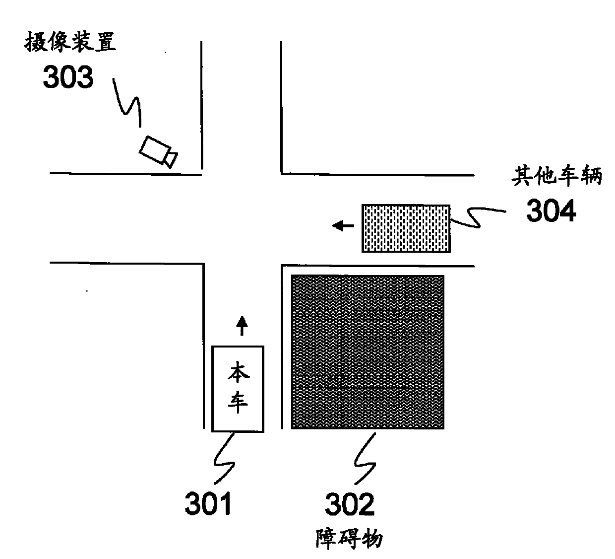
[0007] In addition, in the safety device that embeds the camera in the front bumper of the car, it is easy to grasp the road conditions as long as the monitor in the car is seen, but there is a problem that at least the front bumper must enter the intersection, and it cannot Total avoidance of conflict accidents etc.
At this time, the possibility of traffic accidents is very high and extremely dangerous

Method used


Image

  • Intersection situation recognition system
  • Intersection situation recognition system
  • Intersection situation recognition system

Examples


Embodiment 1

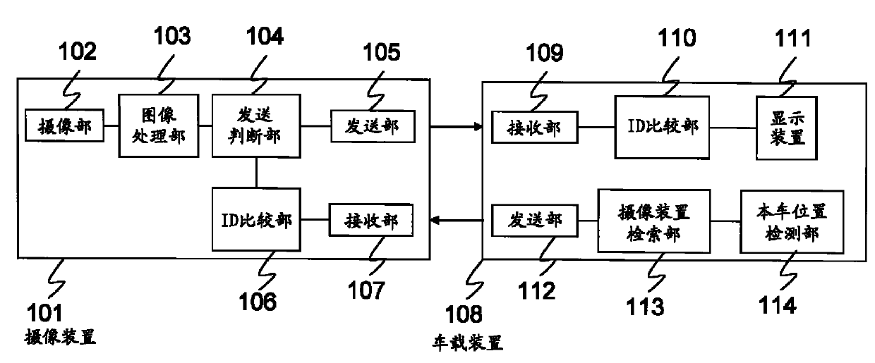
[0100] figure 1 It is a block diagram showing the overall configuration of the intersection state recognition system according to Embodiment 1 of the present invention.

[0101] The intersection recognition system in the first embodiment is composed of an imaging device 101 and an on-vehicle device 108 . The imaging device 101 and the vehicle-mounted device 108 each have a unique identification number (ID). Wireless communication such as light or radio waves is used for communication between the vehicle-mounted device 108 and the imaging device 101 . In addition, the term "identification serial number" also includes symbols other than numbers or identification codes composed of a combination of numbers and symbols other than numbers.

[0102] The imaging device 101 is composed of the following: an imaging unit 102, which has a lens, an imaging element, an analog front end for converting captured images into digital imaging signals, etc.; and performs predetermined processing...

Embodiment 2

[0119] Heretofore, it is assumed that the positions and IDs of imaging devices installed nationwide are recorded in advance in the imaging device search unit 113 , but an example of a case where they are not recorded in advance will be described here.

[0120] Figure 9 It is a block diagram showing the overall configuration of the intersection state recognition system in Embodiment 2 of the present invention. In the overall structure as the embodiment 1 figure 1 In , a sending unit 901 and an imaging device installation information receiving unit 902 are newly added as blocks. Provided figure 1 Among the imaging devices 101 of figure 1 Among the in-vehicle devices 108 of , a device newly added with a block is the in-vehicle device 108A.

[0121] camera device 101A with respect to figure 1 The imaging device 101 of the present invention adds a transmitting unit 901 for transmitting the position information of the device, the shooting direction, and the ID to the surroundi...

Embodiment 3

[0126] In Embodiment 1, when images are received from a plurality of imaging devices, all images are displayed in the same manner, but there are Figure 11A In the case of the illustrated intersection 1106 where obstacles 1104 and 1105 exist and two imaging devices 1101 and 1102 are installed, the priority of the image may change depending on which direction the host vehicle 1103 is traveling. For example in Figure 11A In this case, when the vehicle 1103 wants to go straight at the intersection 1106 and when it wants to turn right, both images on the left and right have the same priority, but when the vehicle 1103 wants to turn left at the intersection 1106, the imaging device 1101 The captured image of the road on the right has a higher priority than the image of the road on the left captured by the imaging device 1102 . In this case, it is preferable to display the image on the right with priority. Figure 11B shows the relationship of the priority of the left and right i...


PUM


Abstract

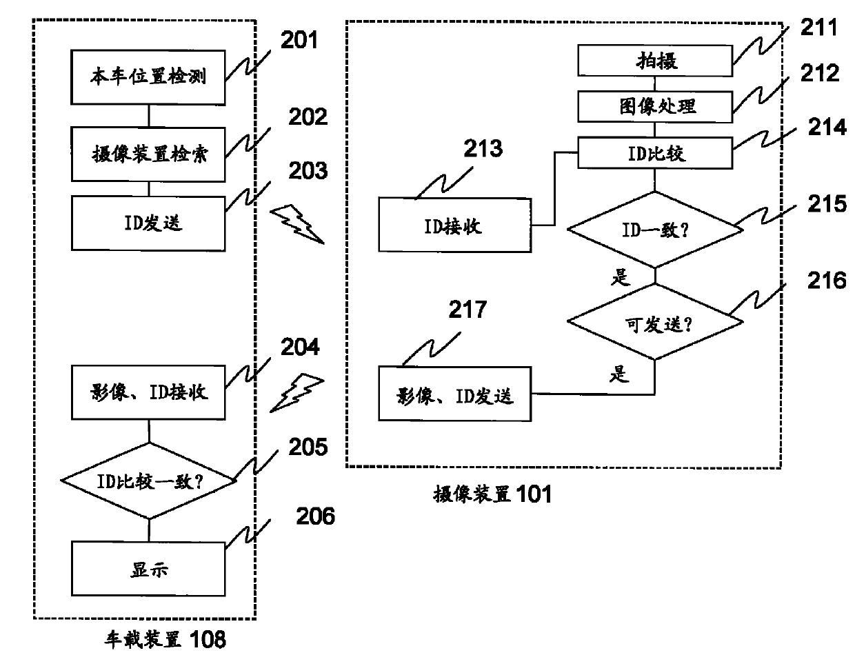
An intersection situation confirmation system which allows reliable grasp of a road situation having a blind area when a vehicle such as an automobile passes through an intersection blind due to an obstacle. An imaging device (101) which captures an image of a direction blind from the vehicle entering the intersection by an imaging section (102) and transmits the captured image to the vehicle entering the intersection is installed in the vicinity of the blind intersection. Moreover, an in-vehicle device (108) which receives the image from the imaging device (101) and displays the image on a display device (111) is installed to the vehicle entering the intersection. The in-vehicle device (108) searches for the imaging device identification number of the imaging device (101) installed at the intersection being entered, transmits the imaging device identification number to the imaging device (101), and displays the received intersection image only when the imaging device identification number received with the intersection image from the imaging device (101) and the searched imaging device identification number match.

Description

technical field [0001] The present invention relates to an intersection situation recognition system that supports safety confirmation when driving a vehicle, and in particular relates to a system that can recognize the movement status of vehicles, people, etc. The system's intersection condition recognition system. Background technique [0002] Usually, at intersections such as curves with poor visibility, T-shaped roads, and intersections, safety devices such as curve mirrors are installed to ensure the field of view in order to allow vehicles such as bicycles, bicycles, and cars to pass safely. [0003] In addition, a safety confirmation device has been developed in which a camera is embedded in the front bumper of a car, and the camera takes a picture of a road that constitutes a blind spot, and displays it on a car navigation monitor in the car. According to this device, even when the road condition that constitutes a blind spot cannot be grasped, such as an intersecti...

Claims


Application Information

Patent Timeline
IPC IPC(8): G08G1/16B60R21/00G08G1/04G08G1/09
CPCG08G1/166G08G1/096783G08G1/04G08G1/167G08G1/16
Inventor 野津拓马小川雅裕高桥显士
Owner PANASONIC CORP
Learn More