
Core mold for spinning and forming large-size complex curved generatrix thin-wall member with transverse inner ribs

A thin-walled component, spinning forming technology, applied in forming tools, metal processing equipment, manufacturing tools, etc., can solve the problems of scratches on the inner wall of the workpiece, damage and scrap, waste of human, material and financial resources, etc., to achieve low manufacturing costs, easy to machine Processed, easy-to-assemble effects

Active Publication Date: 2011-06-15
NORTHWESTERN POLYTECHNICAL UNIV
View PDF5 Cites 19 Cited by
  • Summary
  • Abstract
  • Description
  • Claims
  • Application Information

AI Technical Summary

Problems solved by technology

However, since the internal ribs of the thin-walled spinning parts with horizontal internal ribs are located at the end of the workpiece, the shape of the ribs is close to that of the cylindrical parts. The length of the workpiece needs to be very large. In addition, when forming a large and complex curved generatrix thin-walled workpiece with transverse inner ribs, the wall thickness of the workpiece is very thin. Improper demoulding will cause the inner wall of the workpiece to be scratched or even destroyed, resulting in waste of manpower, material resources and financial resources.

Method used


Image

  • Core mold for spinning and forming large-size complex curved generatrix thin-wall member with transverse inner ribs
  • Core mold for spinning and forming large-size complex curved generatrix thin-wall member with transverse inner ribs
  • Core mold for spinning and forming large-size complex curved generatrix thin-wall member with transverse inner ribs

Examples


Embodiment Construction

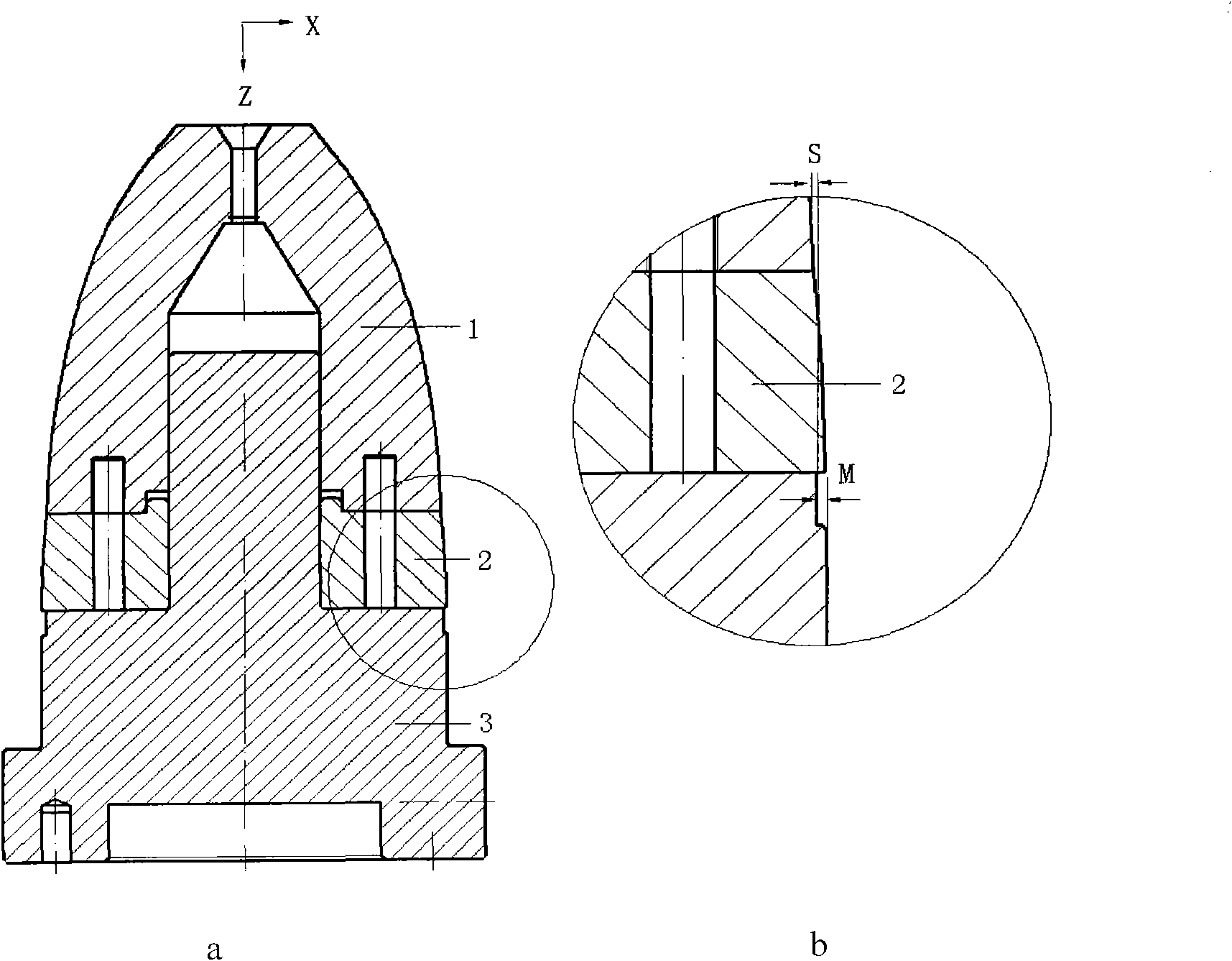
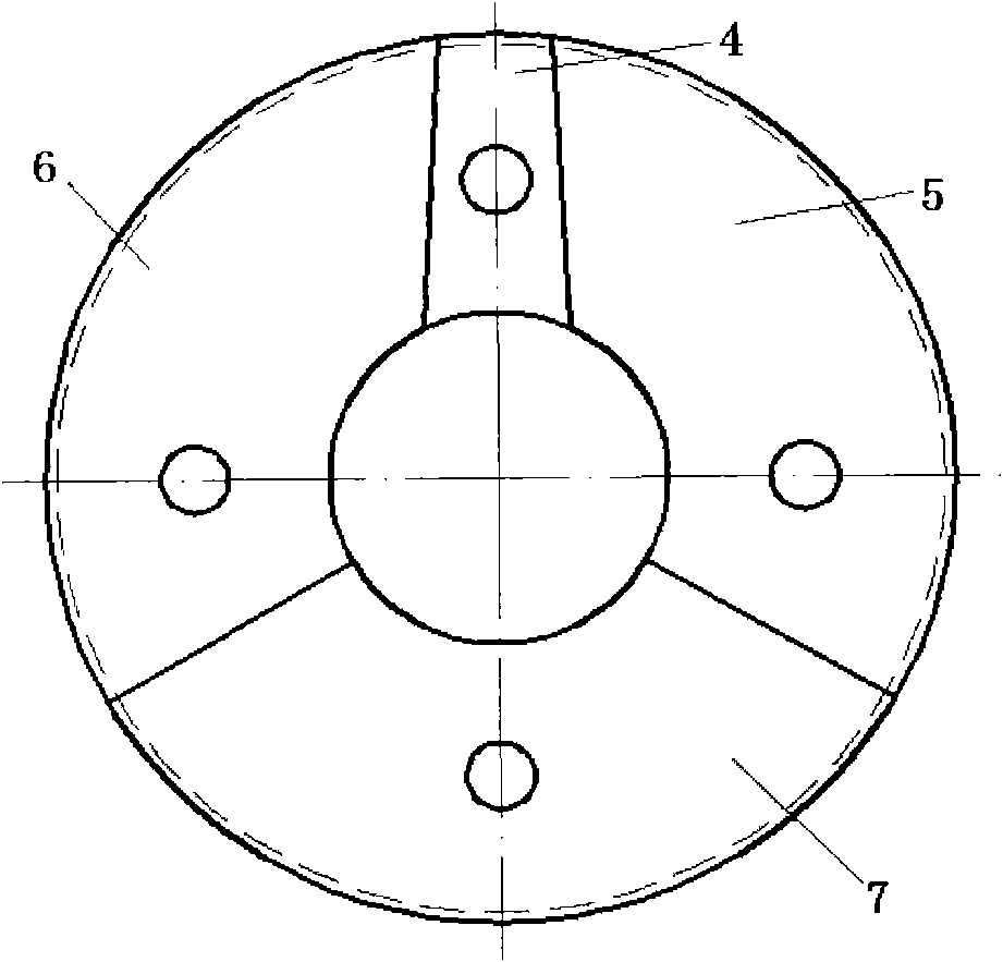
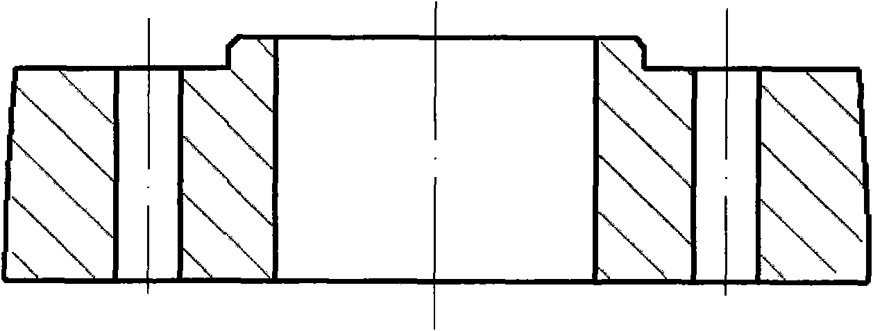
[0024] This embodiment is a horizontal and vertical combined split mold used in the spinning forming of a large complex curved generatrix thin-walled component with horizontal inner ribs. Including mandrel head 1, splint 2 and mandrel tail 3, such as figure 1 As shown, and the mandrel head 1, splint 2 and mandrel tail 3 are all rotary bodies. Among them, the splint 2 is located between the mandrel head 1 and the mandrel tail 3, and is set on the positioning shaft of the mandrel tail 3; the splint 2 and the mandrel head 1 are hollow shells, and the splint 2 and the core The profiles of the die head 1 are all curved generatrix type. The inner hole of the mandrel head 1 is a stepped hole; the diameter of the inner hole at one end of the mandrel head 1 is the same as the outer diameter of the positioning shaft on the mandrel tail 3, forming an assembly hole for the mandrel tail positioning shaft; On the end face of part 1, there is a groove in the assembly hole of the positionin...


PUM


Abstract

The invention relates to a core mold for spinning and forming a large-size complex curved generatrix thin-wall member with transverse inner ribs, wherein a clamping plate is positioned between the head part and tail part of the core mold and sheathed on a positioning shaft at the tail part of the core mold; the clamping plate and the head part of the core mold are hollow shells, and the clamping plate and the head part of the core mold take the shape of a curved generatrix; an aperture of an inner hole at one end of the head part of the core mold is an assembling hole of the positioning shaftat the tail part of the core mold; on the end surface of the core mold, a circle of groove is arranged around the assembling hole at the tail part of the core mold, and used for positioning the clamping plate; a screw hole for hanging the core mold is arranged at the other end of the core mold; and the assembling hole, at the head part of the core mold, of the positioning shaft at the tail part of the core mold, and a hanging hole at the other end of the head part of the core mold are in tapered transition. All the parts of the core mold are rotary parts, and the combined horizontal and longitudinal split technology is adopted for the core mold, therefore, the large-size complex curved generatrix thin-wall members with the transverse inner ribs can be demolded smoothly after spinning and forming. The core mold has the characteristics of easiness of processing and assembly, and low manufacturing cost.

Description

technical field [0001] The invention belongs to the field of spinning forming processing, and in particular relates to the design of a spinning forming mandrel for a large complex curved generatrix thin-walled component with transverse internal ribs. Background technique [0002] After decades of development, spinning technology is now playing an increasingly important role in the near-net shape of thin-walled, complex-shaped, and lightweight integral components. Large complex curved generatrix thin-walled components are a type of parts commonly used in aerospace and weapon industries, such as aircraft engine covers, integral rocket engine components, compressor cones, nose cones of artificial satellites and missiles, and drug types in the weapon industry cover etc. Due to the development of high-tech industries such as aerospace, it is required to improve the strength and rigidity of such parts without affecting the aerodynamic performance of the exterior to optimize the o...

Claims


Application Information

Patent Timeline
IPC IPC(8): B21D37/10B21D22/16
Inventor 詹梅杨合陈飞蒋华兵
Owner NORTHWESTERN POLYTECHNICAL UNIV
Learn More