Machine special for cutting waist-shaped arc groove

A technology of arc groove and special machine, which is applied in the details of milling machine equipment, metal processing equipment, milling machine equipment, etc., can solve the problems of insufficient rigidity, inability to process, low processing efficiency, etc., and achieve high surface roughness, high dimensional accuracy, The effect of high clamping efficiency

Active Publication Date: 2011-06-15
CHANGZHOU TENGLONG AUTO PARTS CO LTD
View PDF4 Cites 7 Cited by
  • Summary
  • Abstract
  • Description
  • Claims
  • Application Information

AI Technical Summary

Problems solved by technology

[0002] In the field of mechanical processing, lathes or milling machines are often used to process arc grooves, but for multi-channel continuous semi-arc grooves, especially waist-shaped arc processing, the processing efficiency of such equipment is low or the function is not enough to process, or Insufficient rigidity cannot be processed, and the dimensional accuracy is not easy to control, so the ideal effect cannot be achieved
In the existing equipment, there is no processing machine specially developed for this type of product, especially in today's highly developed automotive industry, where the demand for parts processing is strong, and many special-shaped asymmetrical rotating parts require the processing of multiple continuous semi-finished parts with small radii. The technological requirements of arc grooves are a bottleneck, and there is an urgent need for an equipment that can solve complex processing conditions such as high clamping efficiency, high clamping rigidity, high chip rigidity, high dimensional accuracy and surface roughness, so as to solve the current A processing dilemma

Method used


Image

  • Machine special for cutting waist-shaped arc groove
  • Machine special for cutting waist-shaped arc groove
  • Machine special for cutting waist-shaped arc groove

Examples


Embodiment Construction

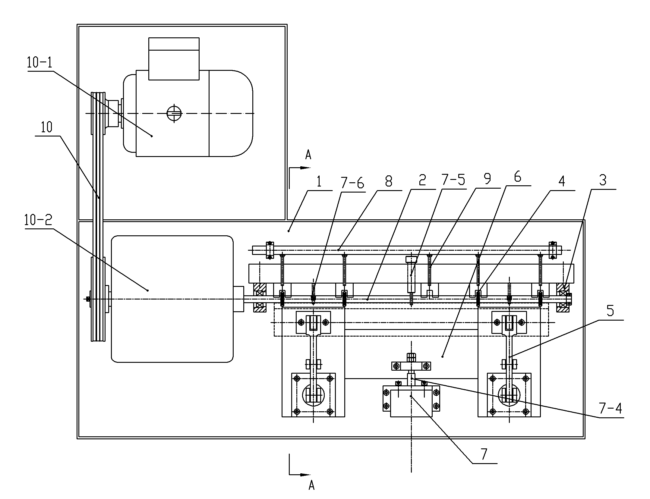
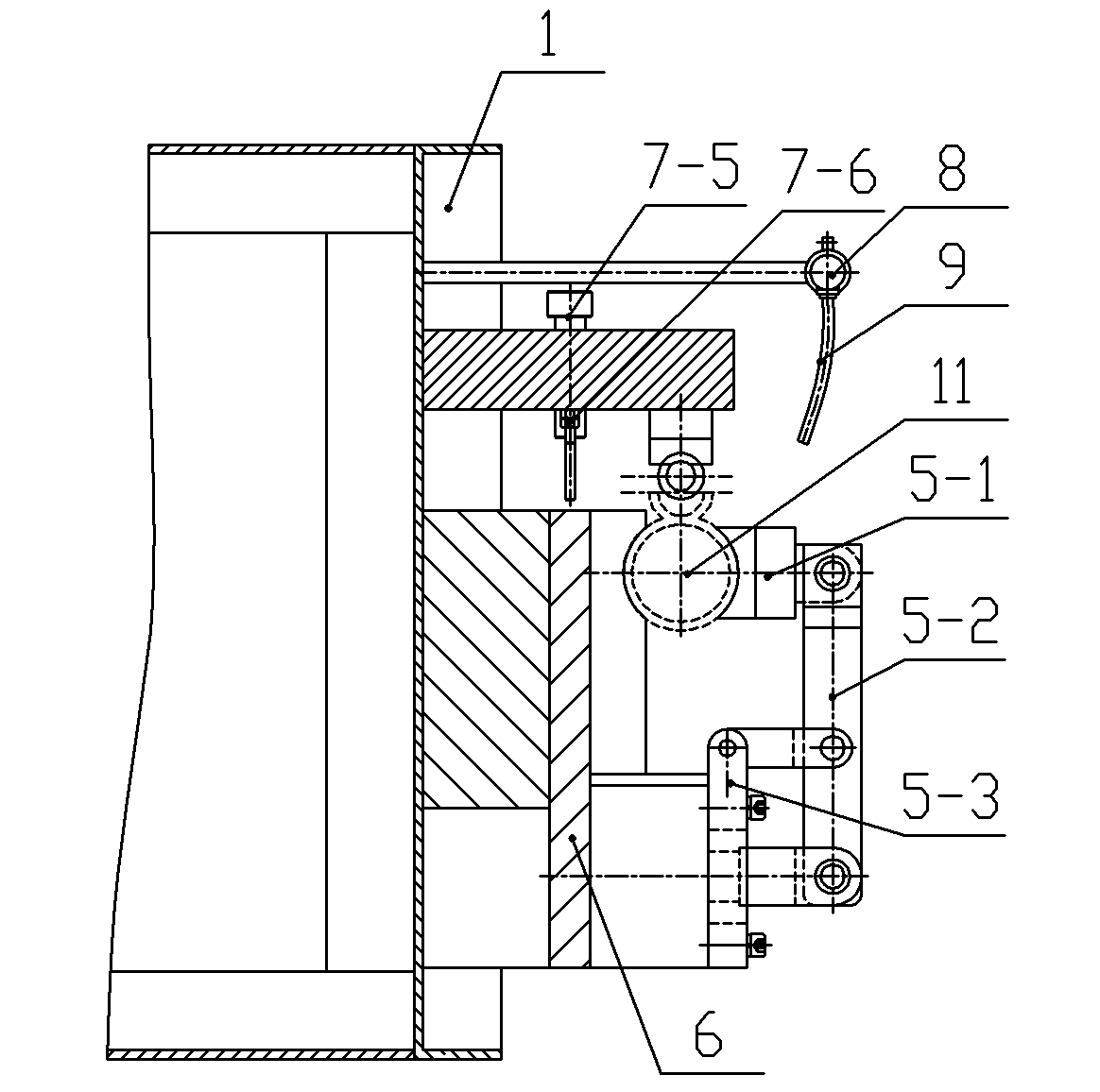
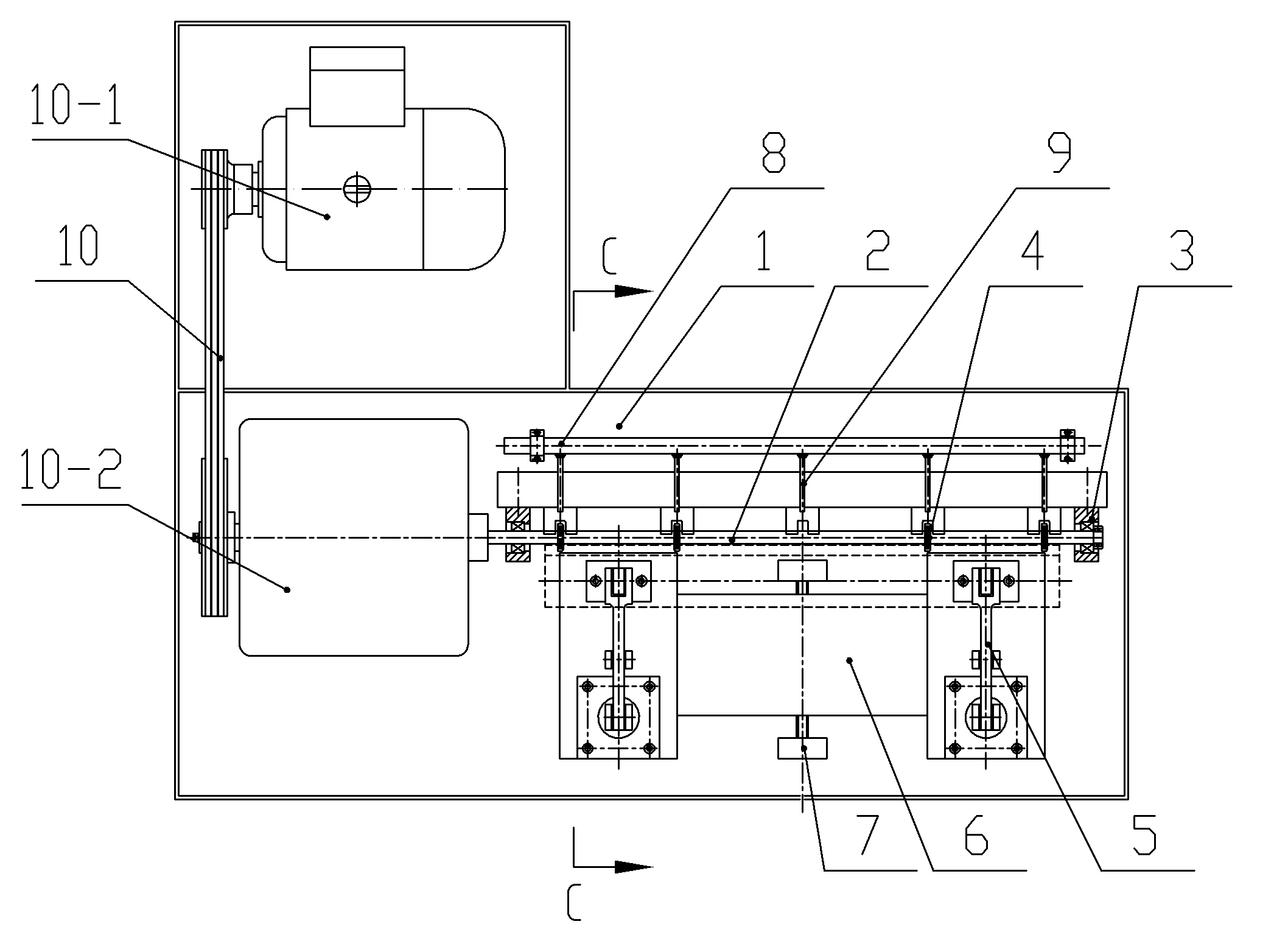
[0020] Such as figure 1 and figure 2 The first embodiment of the waist-shaped circular arc groove grooving machine shown in the present invention includes a workbench 1, a grooving mechanism, a workpiece clamping mechanism 5 for clamping workpieces, and a grooving feed mechanism. The grooving mechanism includes a tool shaft 2 with a grooving tool 4, a power mechanism 10 for transmitting power to the tool shaft 2 to rotate the grooving tool 4 for grooving operations, and a tool shaft bracket 3 for supporting the tool shaft 2 , the power mechanism 10 includes a motor 10-1 and a transmission mechanism 10-2, and the tool shaft 2 is coupled with the output shaft of the transmission mechanism 10-2. The power mechanism 10 and the tool shaft bracket 3 are fixedly installed on the workbench 1; the grooving feeding mechanism includes a carriage 6 and a carriage driving mechanism 7 installed on the workbench 1 for driving the carriage to feed or retreat; Plate driving mechanism 7 comp...


PUM


Abstract

The invention relates to a machine for cutting a groove on a semi-round tube, in particular to a machine special for cutting a waist-shaped arc groove. The machine comprises a workbench, a groove cutting mechanism, a workpiece clamping mechanism, a groove cutting feed mechanism and a cooling mechanism; the groove cutting mechanism comprises a motive power mechanism, a groove cutting cutter, and acutter shaft bracket; the motive power mechanism transfers motive power to the grove cutting cutter to rotate the groove cutting cutter so as to perform groove cutting operation; the workpiece clamping mechanism comprises a workpiece clamping hand, a motive power transfer joint and a motive power device; and the motive power device transfers the motive power to the workpiece clamping hand throughthe motive power transfer joint, and the workpiece clamping hand works to tightly clasp a workpiece. The groove cutting feed mechanism comprises a carriage and a carriage diving mechanism arranged onthe workbench and used for driving the carriage to be fed or retreated; and a workpiece clamping mechanism is arranged on the carriage. The machine can radially cut arc grooves or waist-shaped arc grooves on a cambered surface of the semi-round tube conveniently, efficiently and accurately.

Description

technical field [0001] The invention relates to a semi-circular pipe groove cutting machine, in particular to a waist-shaped arc groove cutting machine, which is specially used for cutting circular arc grooves or waist-shaped arc grooves radially on the arc surface of a semi-circular pipe of a workpiece. Background technique [0002] In the field of mechanical processing, lathes or milling machines are often used to process arc grooves, but for multi-channel continuous semi-arc grooves, especially waist-shaped arc processing, the processing efficiency of such equipment is low or the function is not enough to process, or Insufficient rigidity cannot be processed, and the dimensional accuracy is not easy to control, so the desired effect cannot be achieved. In the existing equipment, there is no processing machine specially developed for this type of product, especially in today's highly developed automotive industry, where the demand for parts processing is strong, and many s...

Claims


Application Information

Patent Timeline
Patent Type & Authority Applications(China)
IPC IPC(8): B23C3/34B23C9/00
Inventor 葛恒超
Owner CHANGZHOU TENGLONG AUTO PARTS CO LTD
Why Eureka
Try Eureka