Turning fixture of cast steel sleeve for lathe

A technology of cast steel sleeves and fixtures, applied in clamping, manufacturing tools, supports, etc., can solve problems affecting product quality and yield, inconvenient use, complex fixture structure, etc., achieve small maintenance, easy disassembly and maintenance , Calibration convenient and accurate effect

Inactive Publication Date: 2011-06-15
胡冠奇
View PDF6 Cites 1 Cited by
  • Summary
  • Abstract
  • Description
  • Claims
  • Application Information

AI Technical Summary

Problems solved by technology

Its surface wear and deformation will directly lead to the quality defects of lateral deformation and longitudinal deflection of the surface of a large number of finished strips when they are wrapped with sleeves, especially when the thickness of the strip is 0.17mm to 0.40mm, the impact is more serious, and it is often used as a sleeve. At the expense of scrapping products with a cylinder radius and thickness of about 100mm, it seriously affects product quality and yield
To effectively eliminate this defect, it can only be solved by turning the concave defect on the surface of the cast steel sleeve. However, when turning the cast steel sleeve, the cast steel sleeve needs to be fixed on the lathe, which requires the use of fixtures. Now Some fixtures have complex structures and are inconvenient to use

Method used


Image

  • Turning fixture of cast steel sleeve for lathe
  • Turning fixture of cast steel sleeve for lathe

Examples


Embodiment Construction

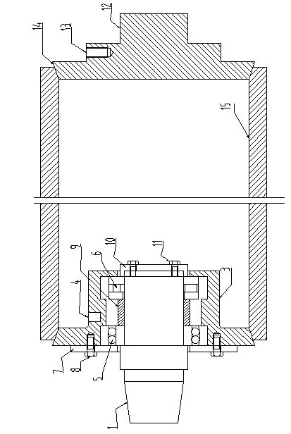
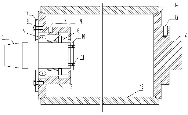
[0017] Such as figure 1 The cast steel sleeve turning fixture for lathes shown includes a bed end fixture and a bed end fixture. The bed end fixture includes a hollow sleeve positioning block 3 and a tapered shaft 1. The positioning edge of the hollow sleeve positioning block 3 is inclined Shaped, hollow sleeve positioning block 3 is provided with lifting ring screw hole 4, which plays a lifting role in the process of loading and unloading the fixture. The row ball bearing 5 and the thrust cylindrical bearing 6 are partly located in the hollow sleeve positioning block 3, and the taper shaft 1 between the double row ball bearing 5 and the thrust cylindrical bearing 6 is provided with a bearing spacer 9, and the hollow sleeve positioning block 3 and The double-row ball bearings 5 ​​are fixed by the bearing gland 7, the bearing gland 7 is fixed on the hollow sleeve positioning block 3 by the bolt 8, and the bearing adjustment gland is arranged between the thrust cylindrical beari...


PUM


Abstract

The invention belongs to the technical field of lathe fixtures, in particular relating to a turning fixture of a cast steel sleeve for a lathe. The fixture comprises a lathe tail end fixture and a lathe head end fixture, wherein the lathe tail end fixture comprises a hollow sleeve positioning block and a taper shaft; the taper shaft is provided with a bearing; the part, which is provided with the bearing, of the taper shaft is positioned in the hollow sleeve positioning block; the lathe head end fixture comprises a sleeve positioning block; the end part of the sleeve positioning block is provided with a lathe chuck clamping bulge end; and the hollow sleeve positioning block and the sleeve positioning block are coaxially arranged, and positioning edges are both oblique. When the turning fixture provided by the invention is used, the taper shaft of the lathe tail end fixture and the lathe chuck clamping device of the lathe head end fixture are fixed at the tail and head of the lathe respectively; the lathe tail end fixture can be adjusted so that the cast steel sleeve rotates along with the lathe spindle without deformation or dislocation under the concentric clamping force at the head and tail of the lathe during a turning process; and in the turning process, the fastening is reliable, the correction is convenient and accurate, the operation is safe and reliable, and the maintenance amount is small.

Description

technical field [0001] The invention belongs to the technical field of fixtures for lathes, and in particular relates to a turning fixture for cast steel sleeves for lathes. Background technique [0002] In the aluminum processing and other non-ferrous metal machining and maintenance industries, the cast steel sleeve with an inner diameter of ¢505mm used in the rolling process of finished coils has a specification length of 1000-2000mm and a thickness of about 25-45mm. The finished coils are used alternately in the multi-pass rolling process of different specifications, and according to the special requirements of the rolling process of some products, at the same time, the products are subjected to technological annealing under high temperature and high pressure. Therefore, the cast steel sleeve not only Frequent instantaneous friction between the bearing surface and the plate, and technological annealing also cause deformation and degradation of various properties of the or...

Claims


Application Information

Patent Timeline
Patent Type & Authority Applications(China)
IPC IPC(8): B23Q3/00
Inventor 李永和胡冠奇牛荟晓李现辉
Owner 胡冠奇
Why Eureka
Try Eureka