
Folding lightweight landing mechanism

A foldable, light-weight technology, applied in the direction of space vehicle landing devices, space vehicle return to the earth's atmosphere, etc., can solve the problems of large volume, high cost, complex buffer structure, etc., to improve carrying capacity, reduce weight, The effect of improving reliability

Inactive Publication Date: 2012-10-17
HARBIN INST OF TECH
View PDF5 Cites 2 Cited by
  • Summary
  • Abstract
  • Description
  • Claims
  • Application Information

AI Technical Summary

Problems solved by technology

[0004] The purpose of the present invention is to solve the problems of large volume, complex buffer structure and high cost in the launch process of the existing landing mechanism, and to provide a foldable light-weight landing mechanism

Method used


Image

  • Folding lightweight landing mechanism
  • Folding lightweight landing mechanism
  • Folding lightweight landing mechanism

Examples


specific Embodiment approach 1

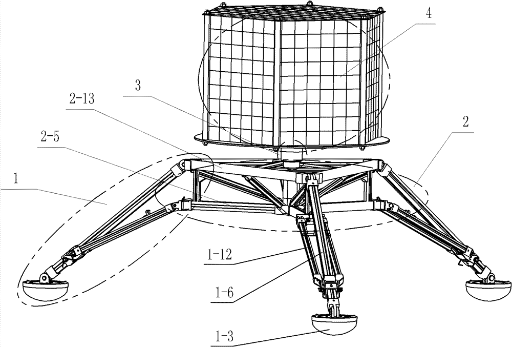
[0018] Specific implementation mode one: combine figure 1 , Figure 3-Figure 12 and Figure 14-Figure 18 Describe this embodiment, the collapsible light-duty landing mechanism of this embodiment includes a triangular space truss type support 2, a buffer assembly 3, an instrument platform 4 and three landing legs 1; the three landing legs 1 are distributed on the triangular space truss type support around 2;

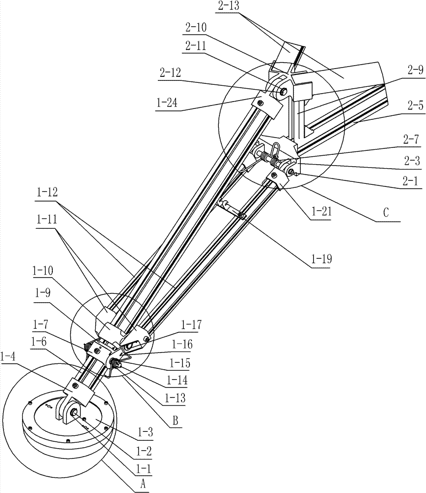
[0019] Each landing leg 1 includes a retaining ring 1-1 at the shaft end of the landing leg, a connecting shaft 1-2 of the landing leg, a landing leg 1-3, a main landing leg joint 1-4, a main landing leg 1-6, and a locking block 1- 7. Two locking parts installation shaft 1-8, slider 1-10, locking spring 1-13, main landing leg space truss bracket joint 1-24, two auxiliary landing leg slider joints 1-11, Two auxiliary landing legs 1-12, two cotter pins 1-14, two locking hook retaining rings 1-15, two locking hooks 1-16, two slider shaft end retaining rings 1-17, two A s...

specific Embodiment approach 2

[0030] Specific implementation mode two: combination Figure 3-Figure 7 Describe this embodiment, the lower end of the main landing leg 1-6 of this embodiment is welded with the main landing leg joint 1-4, the upper end of the main landing leg 1-6 is welded with the main landing leg space truss type support joint 1-24, lock The tight block 1-7 is welded on the lower part of the main landing leg 1-6, the auxiliary landing leg slider joint 1-11 is welded to one end of the auxiliary landing leg 1-12, and the other end of the auxiliary landing leg 1-12 is welded with an auxiliary landing Leg space truss type support joint 1-21, two adjacent ends of two adjacent triangular support rods 2-13 are welded together through a triangular support joint 2-10, and the three star-shaped support rods 2-5 star Arranged in a shape and welded together through the center joint 2-6; the upper end of each connecting pillar 2-9 is welded together with a triangular bracket joint 2-10 through a first c...

specific Embodiment approach 3

[0031] Specific implementation mode three: combination Figure 3-Figure 7 Describe this embodiment, the lower end of the main landing leg 1-6 of this embodiment and the main landing leg joint 1-4 are connected together by screws, and the upper end of the main landing leg 1-6 is connected to the main landing leg space truss type support joint 1-4. 24 are connected together by screws, the locking block 1-7 is fixed on the lower part of the main landing leg 1-6 by screws, and the auxiliary landing leg slider joint 1-11 is connected with one end of the auxiliary landing leg 1-12 by screws The other end of the auxiliary landing leg 1-12 is connected with the auxiliary landing leg space truss type support joint 1-21 by screws, and the two adjacent ends of two adjacent triangular support rods 2-13 are connected with a triangular support joint 2-21 10 are connected together by screws, and the three star-shaped bracket rods 2-5 are arranged in a star shape and connected with the centra...


PUM


Abstract

The invention discloses a folding lightweight landing mechanism and relates to the landing mechanism of a lander. The invention aims at solving the problems of large volume, complexity in a buffer structure and high cost of the existing landing mechanism of the lander during the launching process. The folding lightweight landing mechanism comprises a triangular space truss type support, a buffer component, an instrument platform and three landing legs, wherein the triangular space truss type support comprises a triangular support, a star-shaped support, a space truss connecting rod component,three groups of main landing leg connecting components and three groups of auxiliary landing leg connecting components, the triangular support and the star-shaped support are arranged at the upper part and the lower part, the triangular support is connected with the star-shaped support through the connecting rod component, the three landing legs are distributed and connected on the periphery of the triangular space truss type support through the main landing leg connecting components and the auxiliary landing leg connecting components, and the triangular space truss type support is connected with the instrument platform through the buffer component. The folding lightweight landing mechanism is applicable to lander exploration activities for asteroids, comets, the moon, the Mars and the like.

Description

technical field [0001] The invention relates to a landing mechanism of a lander, in particular to a foldable light-duty landing mechanism, which belongs to the technical field of deep space exploration lander detection. Background technique [0002] At present, humans have explored the moon, Mars, Venus, etc., and launched corresponding landers and rovers to perform sampling and analysis on the surface of stars. The landing mechanism is a necessary condition to ensure the successful landing of the lander. The United States, Russia, Europe, Japan and other countries and regions are in a leading position in lander detection and landing mechanism research. The United States successfully launched the first lander Surveyor 1 on May 30, 1966, which landed softly on the moon. From 1968 to 1968, a total of 7 Surveyor series landers were launched, and 5 of them landed successfully. , this mission provided the necessary technical support and foundation for the subsequent Apollo serie...

Claims


Application Information

Patent Timeline
Patent Type & Authority Patents(China)
IPC IPC(8): B64G1/62
Inventor 赵京东赵志军刘伊威刘宏王金昌
Owner HARBIN INST OF TECH
Learn More