Polysilicon reduction furnace

A reduction furnace and polysilicon technology, applied in the direction of silicon compounds, inorganic chemistry, non-metallic elements, etc., can solve the problems of low output, high energy consumption, high cost, etc., and achieve the effect of improving utilization rate, avoiding damage, and avoiding loss

Active Publication Date: 2011-06-15
王琛茜
View PDF8 Cites 7 Cited by
  • Summary
  • Abstract
  • Description
  • Claims
  • Application Information

AI Technical Summary

Problems solved by technology

[0008] In order to overcome the problems of high cost, huge energy consumption and low output of the polysilicon reduction furnace used in the existing industry, the present invention provides a polysilicon reduction furnace with low cost, low energy consumption and large output

Method used


Image

  • Polysilicon reduction furnace
  • Polysilicon reduction furnace

Examples


Embodiment Construction

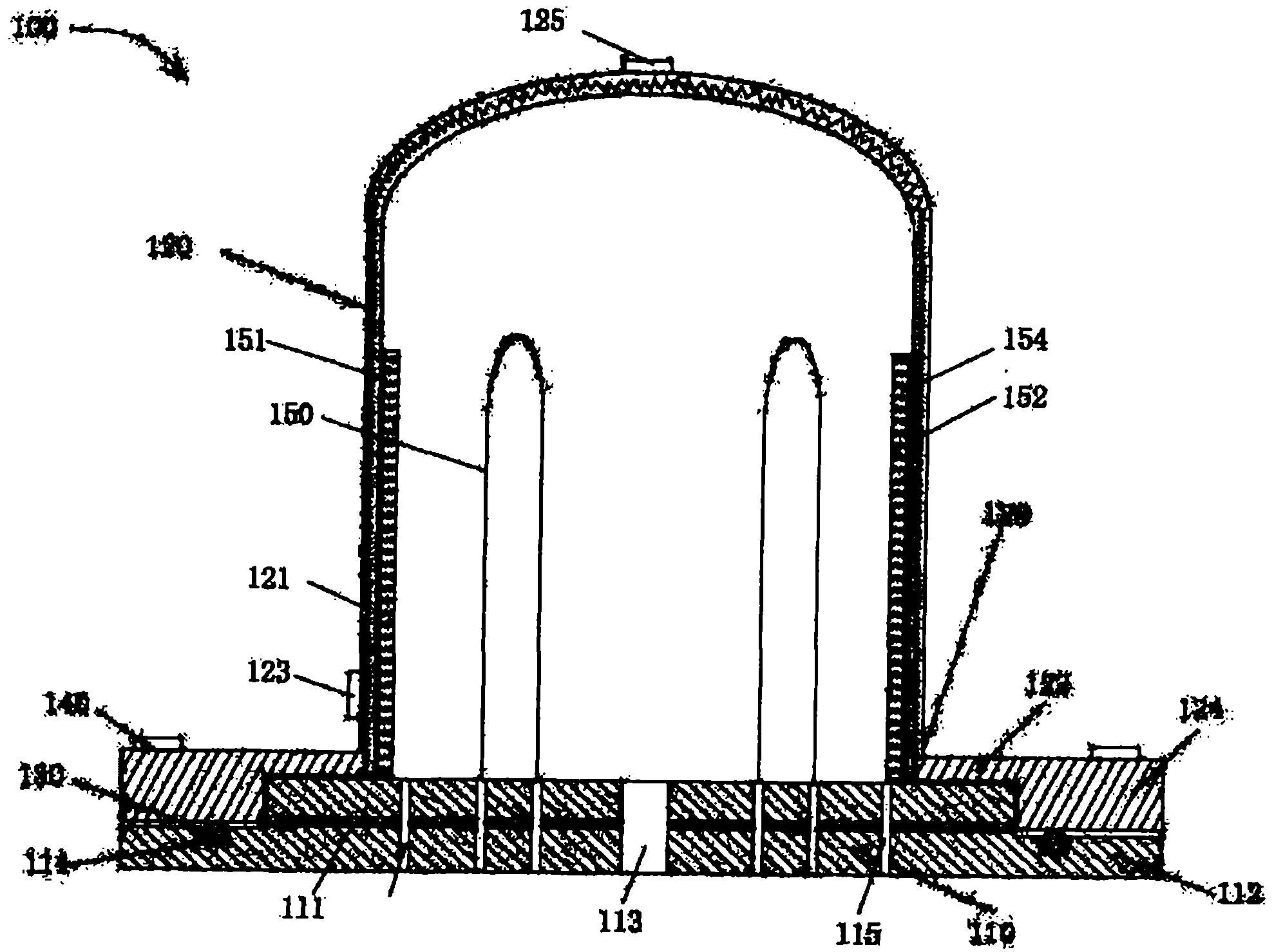
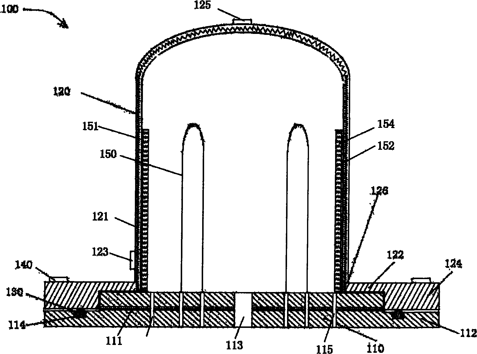
[0022] The specific embodiments of the present invention will be described in detail below with reference to the drawings.

[0023] See figure 1 As shown, the present invention relates to a paracrystalline silicon reduction furnace 100 for producing polysilicon, which includes a base 110 and a furnace body 120 disposed on it. Two U-shaped electrode heaters 150 are fixed on the base 110. The base 110 is also provided with an air inlet 113 and a plurality of air outlets 115. The furnace wall of the furnace body 120 is double-layered, and spirally rising cooling pipes or diversion grooves are arranged between the double-layer furnace walls, and cooling water or cooling oil 121 and cooling water or cooling oil 121 are passed through the cooling pipes or diversion grooves. The inlet 123 is set at the bottom of the furnace body 120, and the outlet 125 is set on the top of the furnace body 120. The cooling water or cooling oil 121 is pressurized by a pump (not shown) to make it flow co...


PUM


Abstract

The invention relates to a polysilicon reduction furnace, which is used for producing polysilicon. The polysilicon reduction furnace comprises a base and a furnace body arranged on the base; and a heat-insulating device is arranged on the inner wall of the furnace body. By arranging the heat-insulating layer on the inner wall of the furnace body, the heat in the furnace body is utilized more effectively.

Description

Technical field [0001] The invention relates to a polysilicon production equipment, in particular to a polysilicon reduction furnace for producing polysilicon. Background technique [0002] With the development of science and technology, the development of solar photovoltaic industry and semiconductor industry has become more and more rapid. As the main raw material of the solar photovoltaic industry and the semiconductor industry, the industrial demand for polysilicon is also increasing. [0003] At present, there are many methods for producing polysilicon in the industry, and the more common one is the hydrogen reduction method. It uses purified trichlorosilane and purified hydrogen as raw materials, and is passed into the reaction vessel. Under high temperature and high pressure, the two chemically react in the reaction vessel to form polysilicon and deposit in the reaction vessel. Inside the heating element. As the chemical reaction continues, more and more polysilicon is de...

Claims


Application Information

Patent Timeline
Patent Type & Authority Applications(China)
IPC IPC(8): C01B33/035
Inventor 王春龙
Owner 王琛茜
Why Eureka
Try Eureka