
Core valve jet-suction hydraulic down-the-hole (DTH) hammer

A technology of jet-suction and down-the-hole hammer, which is applied in the direction of wellbore/well valve device, drilling equipment, wellbore/well parts, etc. The hammer can not meet the requirements, the structure of the down-the-hole hammer is complicated, etc., to achieve the effect of simple structure, easy assembly, disassembly and maintenance, and easy erosion

Active Publication Date: 2013-05-29
昆明国经液压锤制造有限公司
View PDF5 Cites 0 Cited by
  • Summary
  • Abstract
  • Description
  • Claims
  • Application Information

AI Technical Summary

Problems solved by technology

The diversion will inevitably lead to a complex structure of the DTH hammer, an increase in useless energy consumption, and also bring some other technical problems
[0003] The liquid energy utilization rate of the jet-suction hydraulic DTH hammer is low, and most of the liquid energy cannot be utilized by the piston, but is discharged through the liquid discharge channel into the drilling tool below the anvil, so this DTH hammer has a large pump volume without split flow Potential conditions, the existing jet-suction hydraulic DTH hammers are all sleeve-valve jet-suction valve control mechanisms, such as SX hydraulic impactor and HSX hydraulic DTH hammer, according to the pump volume required by oil drilling, the existing DTH hammer far from meeting the requirements

Method used


Image

  • Core valve jet-suction hydraulic down-the-hole (DTH) hammer
  • Core valve jet-suction hydraulic down-the-hole (DTH) hammer
  • Core valve jet-suction hydraulic down-the-hole (DTH) hammer

Examples


Embodiment Construction

[0023] Specific embodiments of the present invention will be described in detail below in conjunction with the accompanying drawings.

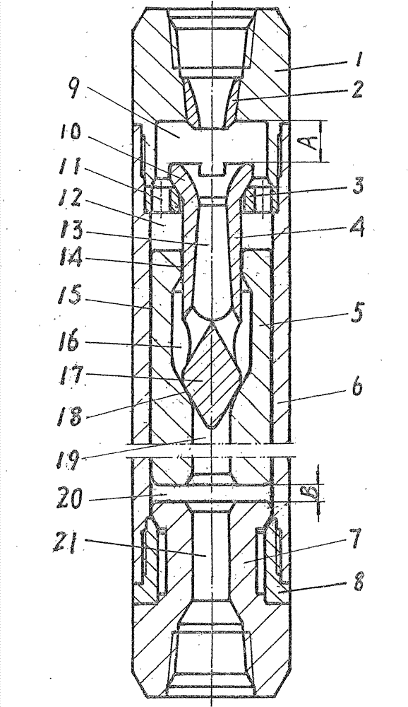
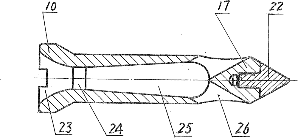
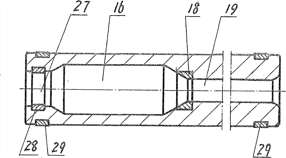
[0024] Such as Figure 1-3 As shown, the core valve jet-suction hydraulic down-the-hole hammer provided by the present invention is composed of an upper joint 1, a nozzle 2, a valve stroke seat 3, a core valve 4, a piston 5, a casing 6, an anvil 7 and a transmission sleeve 8 All the parts are installed on the same axis from top to bottom, from inside to outside. The valve stroke seat, core valve, piston and shell constitute the core valve injection-suction valve control mechanism. The valve stroke seat of this mechanism is fixed on the upper joint. At the connection with the shell, an injection and suction cavity is formed between the inner cavity of the upper joint and the valve stroke seat, and the working fluid is injected from the nozzle through the injection and suction cavity into the inner cavity of the core valve; the core valve is sha...


PUM


Abstract

The invention provides a core valve jet-suction hydraulic down-the-hole (DTH) hammer. The DTH hammer is characterized in that a valve stroke seat, a core valve and a piston which are positioned below a nozzle are sequentially arranged in a shell from the top down to form a core valve jet-suction valve control mechanism, wherein, the valve stroke seat directly controls the stroke of the core valve and free stroke of the piston; the core valve has the functions of a valve as well as a sprayer and can serve as a control element and an energy conversion element for converting kinetic energy of an operating fluid into pressure energy; and the piston is an executive component for converting liquid energy into mechanical energy to impact a hammering block to apply work, and meanwhile the piston is also a control element which is matched with the core valve to realize reciprocating impact motion. The DTH hammer has the advantages that the operating pump volume borne by the DTH hammer is 3-5 times as much as the existing jet-suction hydraulic DTH hammer with the same specification, and operating pressure drop is 0.5-1.5MPa, thus being a splitless hydraulic DTH hammer which can use high-density mud and has the advantages of high pump volume and low pressure drop; and the DTH hammer is applicable to a rotary drilling process of large-aperture drilling engineering such as petroleum drilling, water well drilling and the like, and particularly applicable to a rotary drilling process for high-pump-volume high-viscosity construction by utilizing the drilling mud.

Description

technical field [0001] The invention relates to the field of drilling machinery, in particular to a core valve jet-suction hydraulic down-the-hole hammer used in the rotary percussion drilling technology of drilling engineering. Background technique [0002] The hydraulic down-the-hole hammer has multiple action principles such as positive action, reverse action, double action and compound action. These down-the-hole hammers are used in drilling projects with large pump volumes. It is difficult to accommodate the pump volume required for drilling, so designers often use split flow to solve it. The shunting will inevitably lead to a complex structure of the down-the-hole hammer, increase the useless energy consumption, and also bring some other technical problems. [0003] The liquid energy utilization rate of the jet-suction hydraulic DTH hammer is low, and most of the liquid energy cannot be utilized by the piston but is discharged through the liquid discharge channel into...

Claims


Application Information

Patent Timeline
Patent Type & Authority Patents(China)
IPC IPC(8): E21B4/14E21B34/06
Inventor 刘国经
Owner 昆明国经液压锤制造有限公司
Learn More