Method for directed induction fracturing grouting in shallow tunnel

A directional induction, shallow buried tunnel technology, applied in the direction of tunnel, tunnel lining, earthwork drilling, etc., can solve the problems of running grouting, difficult to complete the water plugging reinforcement, uneconomical, etc., saving grouting time and enhancing controllability , the effect of improving the accuracy

Inactive Publication Date: 2011-06-15
BEIJING JIAOTONG UNIV
View PDF3 Cites 5 Cited by
  • Summary
  • Abstract
  • Description
  • Claims
  • Application Information

AI Technical Summary

Problems solved by technology

For the splitting grouting in the weathered cracked rock-soil layer, due to the randomness of the ground stress and cracks, it is often difficult to split the splitting direction in this type of rock-soil layer according to the actual required direction, so the grouting in this type of layer There are often accidents of grout running and leaking in split grouting, so it is difficult to complete the task of water blocking and reinforcement
The solution to this problem in engineering is to increase the grouting pressure so that the grouting hole is split twice or multiple times to form multiple grout veins to strengthen the formation and waterproof and seepage prevention, but this method has Obvious blindness, and it is very time-consuming and slurry, uneconomical, and for urban shallow buried underground projects, if the operation is not done properly, the surface will bulge, which is very dangerous

Method used


Image

  • Method for directed induction fracturing grouting in shallow tunnel
  • Method for directed induction fracturing grouting in shallow tunnel

Examples


Embodiment approach 1

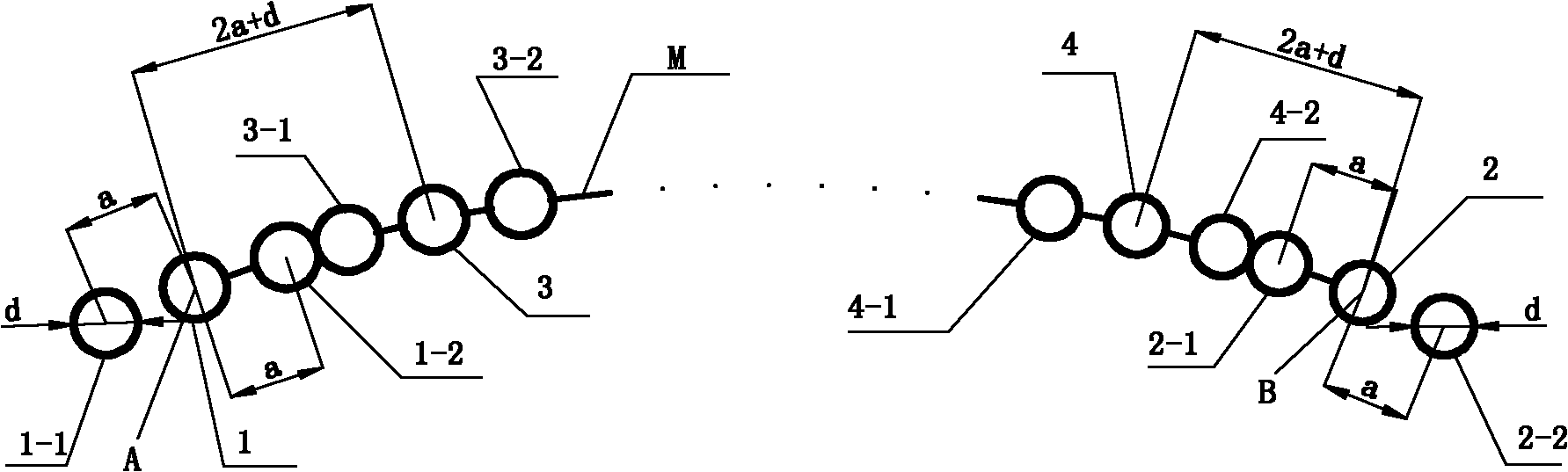
[0023] A directional induced splitting grouting method in a shallow buried tunnel, the induced splitting grouting method comprising the following steps:

[0024] Step 1, select the grouting contour line AB on the tunnel face, determine the number of grouting holes on the grouting contour line AB N=L / (2a+d)+1, L is the length of the grouting contour line AB, d is the diameter of all grouting holes and all induction holes, a is the distance between the center of the grouting hole and the center of the corresponding induction hole;

[0025] Step 2, taking an end point A of the grouting contour line as the center, drilling the first grouting hole 1, the diameter of the first grouting hole 1 is d;

[0026] Step 3, on the extension line of the grouting contour line AB on the left side of the first grouting hole 1, at a distance from the end point A of the grouting contour line, drill the first induction hole 1-1 with a diameter of d; On the grouting contour line AB on the right sid...

Embodiment approach 2

[0039] Grouting is performed within the range of 88.6° above the tunnel, the grouting contour line is arc-shaped, the radius is 2.5m, the diameter d of the grouting hole and the induction hole is 42mm, the depth of the hole is 10m, and the center of the grouting hole corresponds to The distance a between the centers of the induction holes is 1.5d=63mm.

[0040] A directional induced splitting grouting method in a shallow buried tunnel, the induced splitting grouting method comprising the following steps:

[0041] Step 1: Select the grouting contour line AB on the tunnel face, the length of the grouting contour line AB is L=2.5m×88.6×π / 180=3864mm, and determine the number of grouting holes on the grouting contour line AB= L / (2a+d)+1=3864mm / (2×63mm+42mm)+1=24;

[0042] Step 2, taking an end point A of the grouting contour line as the center, drilling the first grouting hole 1, the diameter of the first grouting hole 1 is 42mm;

[0043]Step 3, on the extension line of the grout...

Embodiment approach 3

[0056] Grouting within 120° above the tunnel, the grouting contour line is arc-shaped, the radius is 4.76m, the diameter d of the grouting hole and the induction hole are both 80mm, and the depth of the hole is 12m, and the center of the grouting hole corresponds to it The distance a between the centers of the induced holes is 2d=160mm.

[0057] A directional induced splitting grouting method in a shallow buried tunnel, the induced splitting grouting method comprising the following steps:

[0058] Step 1: Select the grouting contour line AB on the tunnel face, the length of the grouting contour line AB is L=2.5m×120×π / 180=10000mm, and determine the number of grouting holes on the grouting contour line AB= L / (2a+d)+1=10000mm / (2×160mm+80mm)+1=26;

[0059] Step 2, taking an end point A of the grouting contour line as the center, drilling the first grouting hole 1, the diameter of the first grouting hole 1 is 80mm;

[0060] Step 3, on the extension line of the grouting contour l...


PUM


Abstract

The invention discloses a method for directed induction fracturing grouting in a shallow tunnel, which belongs to the field of tunnel and underground engineering. The directed induction fracturing grouting is performed by the method, so that the grouting aim of economic, safe and effective water-blocked reinforcement is fulfilled. The method comprises the following steps of: drilling a first grouting hole at one end point (A) of a grouting profile line, drilling a first inducing hole and a second inducing hole respectively at positions which are 1.5d to 2d away from the two sides of the grouting hole, sealing, grouting to the grouting hole, and fracturing on the connecting lines of the grouting hole and the circle centers of the two inducing holes; and drilling a hole by the same method at the other end point (B) of the grouting profile line, and grouting so as to realize directed grouting. A third grouting hole is drilled at a position which is 4d to 5d away from the first grouting hole, and the process which is performed on the first grouting hole is repeated in the same way, so that the slurry of the inducing holes can be connected; the overall grouting profile line is accomplished according to the processes, so that the overall grouting curtain can be formed; and a fracturing direction in the fracturing grouting is started from a designed direction, so that the limited slurry can be injected into the position at which the slurry is most needed by only fracturing for one time.

Description

technical field [0001] The invention relates to a splitting grouting construction technology in rock and earth underground engineering, and is suitable for splitting grouting construction in shallow buried tunnels. Background technique [0002] Grouting refers to the injection of grout with a certain gel time (that is, the liquid mixture of the main agent, solvent and admixture) into the cracks of the loose soil layer or water-bearing rock layer by means of pressure feeding, and the particles of the consolidated soil after the grout coagulates or Filling the cracks in the rock formation improves the mechanical properties of the rock and soil layer. It is often used for water blocking and reinforcement in water conservancy projects, foundation pit projects, tunnels and underground projects. Commonly used grouting methods can be divided into infiltration grouting, compaction grouting, filling grouting, and splitting grouting according to the grout distribution state. For dens...

Claims


Application Information

Patent Timeline
Patent Type & Authority Applications(China)
IPC IPC(8): E21D11/10E02D3/12
Inventor 黄明利吕奇峰谭忠盛裴书锋霍亚超
Owner BEIJING JIAOTONG UNIV
Why Eureka
Try Eureka