
Variable rotor oil pump regulated and controlled by wave wheel

A technology of rotor oil pump and impeller, applied in the direction of lubricating pump, mechanical equipment, engine components, etc., can solve the problems of increasing engine power loss, reducing engine economy, and increasing lubricating oil temperature, reducing conveying resistance, The effect of reducing oil pressure and reducing power consumption

Inactive Publication Date: 2011-06-15
HUNAN OIL PUMP
View PDF7 Cites 9 Cited by
  • Summary
  • Abstract
  • Description
  • Claims
  • Application Information

AI Technical Summary

Problems solved by technology

As the oil pressure continues to increase, the temperature of the lubricating oil will rise and the viscosity will decrease, which will affect the lubricating effect of the oil and the safe operation of the engine.
In order to solve the problem of oil temperature rise and viscosity drop, a pressure limiting valve is generally used to control the flow and pressure of the oil pump to ensure the normal operation of the engine, but the engine power loss will be increased and the engine economy will be reduced during use. sex

Method used


Image

  • Variable rotor oil pump regulated and controlled by wave wheel
  • Variable rotor oil pump regulated and controlled by wave wheel
  • Variable rotor oil pump regulated and controlled by wave wheel

Examples


Embodiment Construction

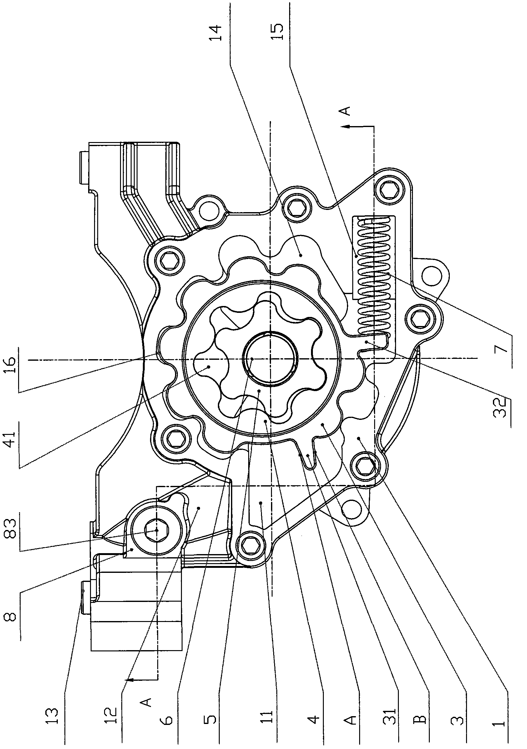
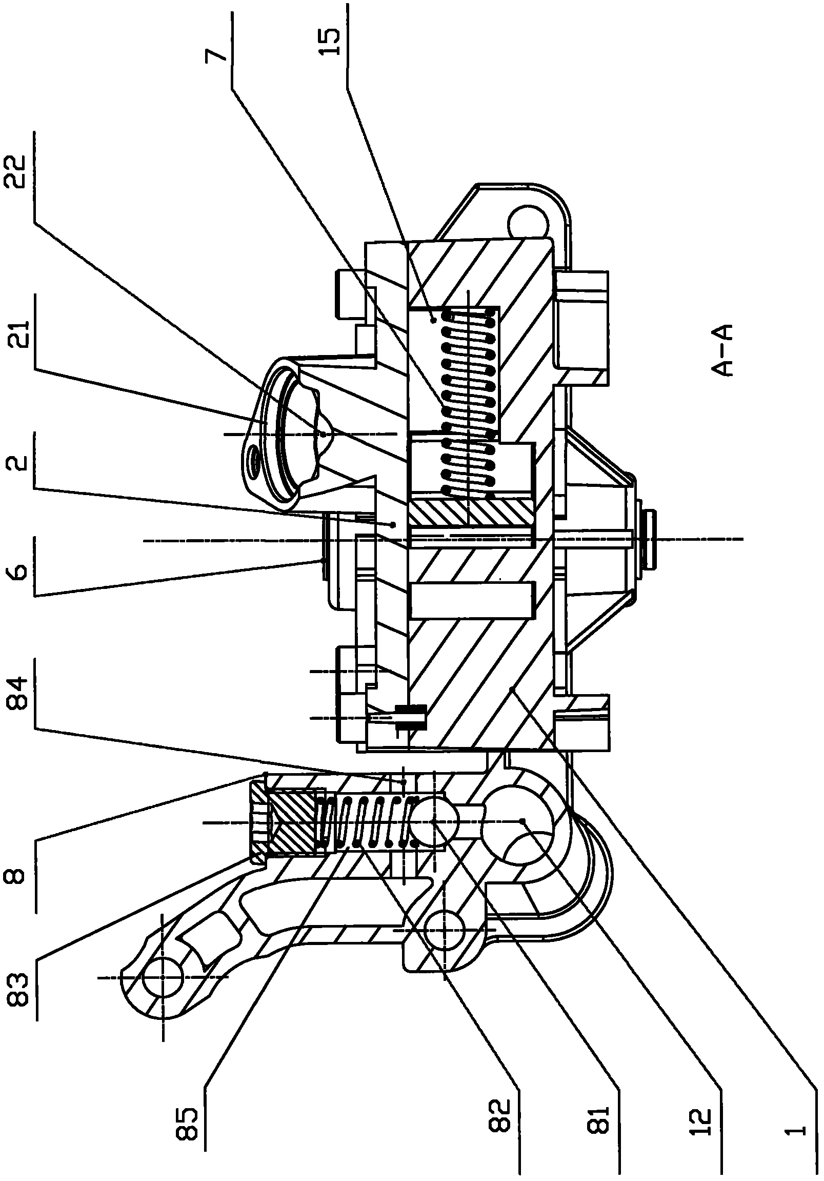
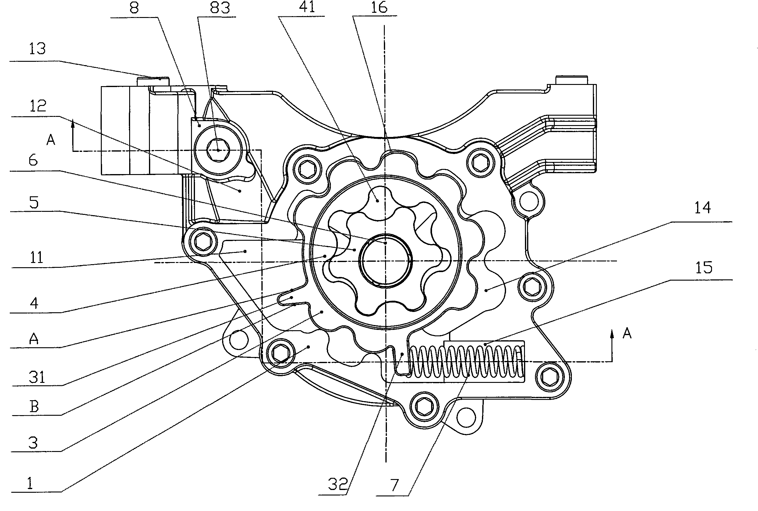
[0012] A variable rotor oil pump regulated by a pulsator, which is composed of a pump body 1, a pump cover 2, a pulsator regulating ring 3, an outer rotor 4, an inner rotor 5, a transmission shaft 6, a spring 7 and a safety valve component 8. The pulsator regulating ring 3 and the spring 7 are installed in the pulsator ring hole 16 and the spring slot 15 on the pump body 1. The middle part of the transmission shaft 6 is in an interference fit with the inner rotor 5, and is installed on the pulsator together with the outer rotor 4. The middle hole on the control ring 3 and the shaft hole of the pump body 1 and the pump cover 2. The two sides and bottom surface of the impeller ring hole 16 in the pump body 1 are provided with an oil inlet cavity 14 and an oil outlet cavity 11, an oil outlet 12 and an oil outlet 13, and the oil outlet 13 communicates with the oil passage of the engine. The outer side of the pulsator control ring 3 is provided with a leaf valve 31 and a return val...


PUM


Abstract

The invention discloses a variable rotor oil pump regulated and controlled by a wave wheel. The variable rotor oil pump is composed of a pump body, a pump cover, a wave wheel regulating and controlling ring, an outer rotor, an inner rotor, a transmission shaft, a spring and a safety valve component, wherein the pump body and the pump cover are connected through a bolt; the wave wheel regulating and controlling ring and the spring are installed in a wave wheel ring hole and a spring groove hole which are positioned on the pump body, the middle part of the transmission shaft is in interference fit with the inner rotor, and the transmission shaft, the inner rotor and the outer rotor are installed in an intermediate hole on the wave wheel regulating and controlling ring and the shaft holes of the pump body and the pump cover; two sides and bottom surface of the wave wheel ring hole of in the pump body are provided with an oil inlet chamber, an oil outlet chamber, an oil outlet duct and an oil outlet, and the oil outlet is communicated with the oil duct of an engine; the oil outlet duct of the pump body is provided with the safety valve hole, the safety valve hole is communicated with the oil outlet duct, the passageway of the safety valve hole is provided with an oil drainage hole, and the safety valve hole is internally provided with the safety valve component; and the combination surface of the pump cover and the pump body is provided with an oil inlet duct and an oil inlet, the oil inlet is communicated with an oil absorption device, and the oil inlet duct is communicated with the oil inlet chamber of the pump body.

Description

technical field [0001] The invention relates to an oil pump in a lubricating system of an internal combustion engine, in particular to a variable rotor oil pump controlled by a pulsator. Background technique [0002] The oil pump used in the existing engine is a quantitative oil pump. As the engine speed increases, the oil supply of the oil pump will continue to increase, and the oil pressure in the oil passage will continue to increase. With the continuous increase of the oil pressure, the lubricating oil temperature will rise and the viscosity will drop, which will affect the lubricating effect of the oil and the safe operation of the engine. In order to solve the problem of oil temperature rise and viscosity drop, a pressure limiting valve is generally used to control the flow and pressure of the oil pump to ensure the normal operation of the engine. sex. SUMMARY OF THE INVENTION [0003] The object of the present invention is to overcome the above-mentioned deficienc...

Claims


Application Information

Patent Timeline
Patent Type & Authority Applications(China)
IPC IPC(8): F16N13/20F16N23/00
Inventor 许仲秋刘光明李战训
Owner HUNAN OIL PUMP
Learn More