Time-domain ground-air electromagnetic detection system and calibration method

An electromagnetic detection, time domain technology, applied in the direction of special electromagnetic/magnetic detection, geophysical measurement, instruments, etc. in the transportation process, can solve the problem that the minimum resolution of the electromagnetic detection system is not comparable, does not have the same standard, and the instrument is stable. Problems such as difficulty in guaranteeing repeatability and repeatability

Inactive Publication Date: 2011-06-15
JILIN UNIV
View PDF9 Cites 47 Cited by
  • Summary
  • Abstract
  • Description
  • Claims
  • Application Information

AI Technical Summary

Problems solved by technology

Since these testing methods cannot accurately calculate the theoretical electromagnetic response of the ore body, they can only qualitatively judge abnormalities based on the measured profile curves to verify the effectiveness of the measurement system detection; known mining area", so the cost of the experiment is relatively high, and it is also necessary to prevent accidental dangers
These experiments cannot simulate other different geoelectric models, so they are not universal
[0007] To sum up the above, the existing technology only proposes the ground-space electromagnetic detection method, and there is no test and calibration of the time-domain ground-space electromagnetic detection system. Moreover, the time-domain electromagnetic detection systems developed by different countries and companies must have differences and differences in performance. characteristics, various electromagnetic detection systems are not comparable in minimum resolution, signal-to-noise ratio, etc. not the same standard

Method used


Image

  • Time-domain ground-air electromagnetic detection system and calibration method
  • Time-domain ground-air electromagnetic detection system and calibration method
  • Time-domain ground-air electromagnetic detection system and calibration method

Examples


Embodiment Construction

[0052] Below in conjunction with accompanying drawing and embodiment do further detailed description:

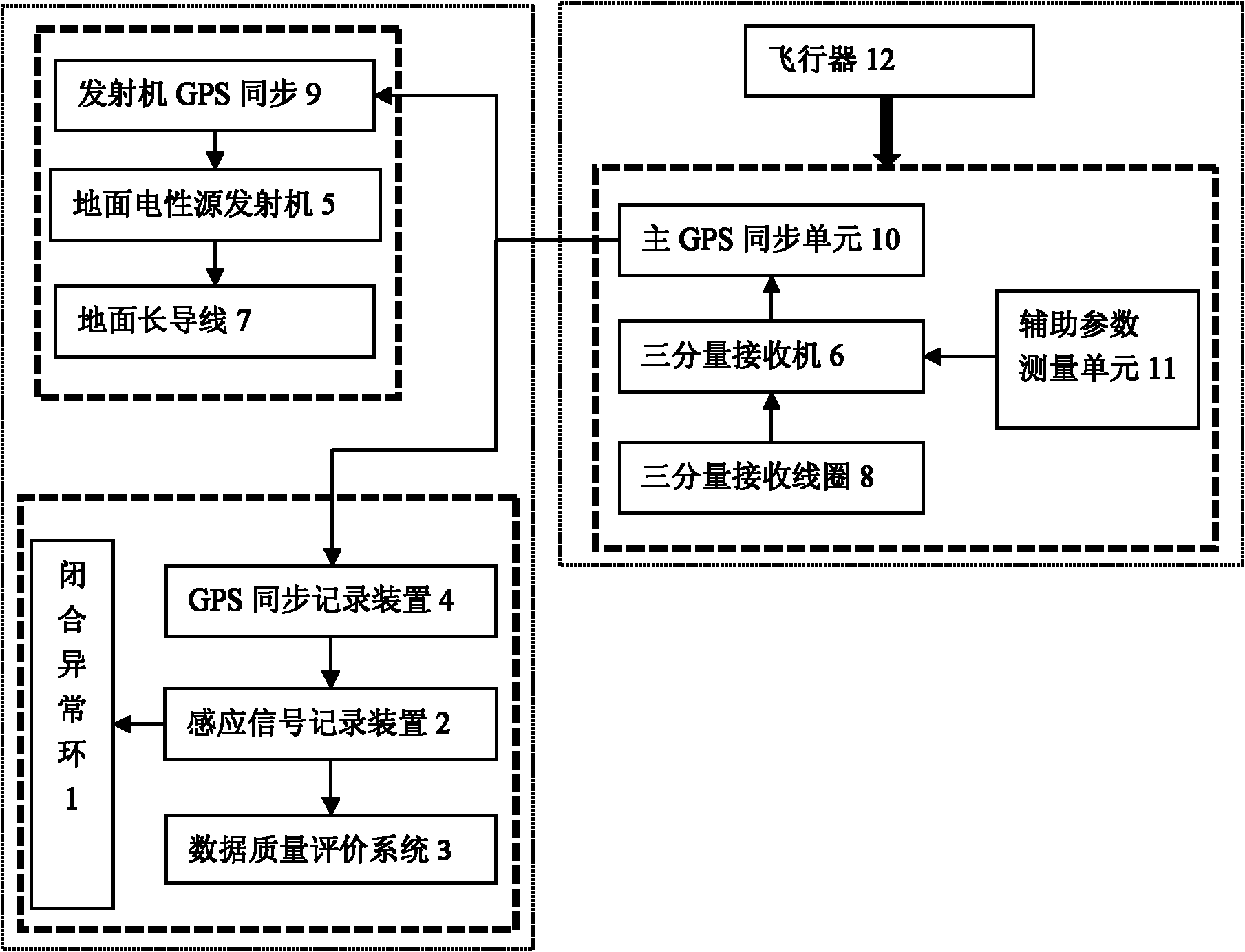
[0053] The time-domain ground-air electromagnetic detection system, the air part is composed of the main GPS synchronization unit 10 carried by the aircraft 12, the three-component receiver 6, the three-component receiving coil 8 and the auxiliary parameter measurement unit 11, and the ground is composed of the transmitter GPS synchronization unit 9 , ground electrical source transmitter 5 and ground long wire 7, induction signal recording device 2 connected to GPS synchronous recording device 4, closed abnormal loop 1 and data quality evaluation system 3 constitute.

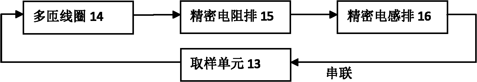
[0054] The closed abnormal loop 1 is a closed loop composed of a multi-turn coil 14 connected in series through a precision resistor bank 15 , a precision inductor bank 16 and a sampling unit 13 .

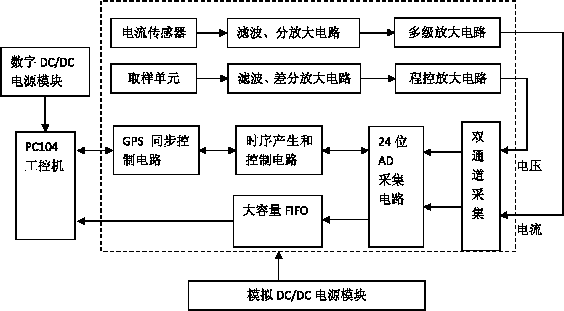
[0055] The induction signal recording device 2 is connected with the PC104 industrial computer by the digital DC...


PUM


Abstract

The invention relates to a time-domain ground-air electromagnetic detection system and a calibration method, in particular to a system consisting of an induction signal recording device connected with a ground recording device global position system (GPS) synchronization unit, a closed abnormal ring and a data quality evaluation system, and a calibration method for the time-domain ground-air electromagnetic detection system. The closed abnormal ring and the induction signal recording device are adopted, the induction current and induction voltage are simultaneously recorded, and the 24-bit 200Hz sampling rate, a bandwidth of 0-13KHz and a dynamic range of an amplifier of 160dB are achieved. Moreover, the system is synchronous with a ground transmitter and an air receiver GPS, and during measurement, by removing earth background field data, a pure closed abnormal ring electromagnetic signal containing a geometric error is extracted, is input into the data quality evaluation system, andis compared and fitted with the computed closed abnormal ring theoretical value, the system error, the geometric parameter error and the detection resolution of the time-domain ground-air electromagnetic detection system are determined, and the performance of the electromagnetic detection system is tested and calibrated.

Description

Technical field: [0001] The invention relates to a geophysical instrument exploration instrument and calibration, in particular to a time-domain ground-space electromagnetic detection system and a calibration method. Background technique: [0002] The ground-air electromagnetic detection method has the advantages of high signal-to-noise ratio, good spatial resolution, convenient field construction, economy, and high efficiency. , Large depth detection. [0003] Australia 847270G01V003116 discloses the method of aerial reconnaissance through the transition process method of laying loops on the ground. A transmitting device is placed on the pre-determined target body on the ground to emit a transitional electromagnetic pulse. The flying instrument with the receiver flies over the receiving device in the measured area. Measure the electromagnetic field caused by the above-mentioned transitional electromagnetic pulse, form a signal and an instantaneously measurable electromagne...

Claims


Application Information

Patent Timeline
Patent Type & Authority Applications(China)
IPC IPC(8): G01V3/17G01V13/00
Inventor 嵇艳鞠林君王远许洋铖曹婧华王言章符磊田培培
Owner JILIN UNIV
Why Eureka
Try Eureka