Laser mirror assembly

A mirror and assembly technology, applied in laser welding equipment, optics, optical components, etc., can solve problems such as reducing production efficiency, and achieve the effect of improving efficiency, convenient operation, and ensuring accuracy

Active Publication Date: 2015-01-28
江苏扬力数控机床有限公司
View PDF5 Cites 0 Cited by
  • Summary
  • Abstract
  • Description
  • Claims
  • Application Information

AI Technical Summary

Problems solved by technology

This greatly reduces production efficiency

Method used


Image

  • Laser mirror assembly
  • Laser mirror assembly
  • Laser mirror assembly

Examples


Embodiment Construction

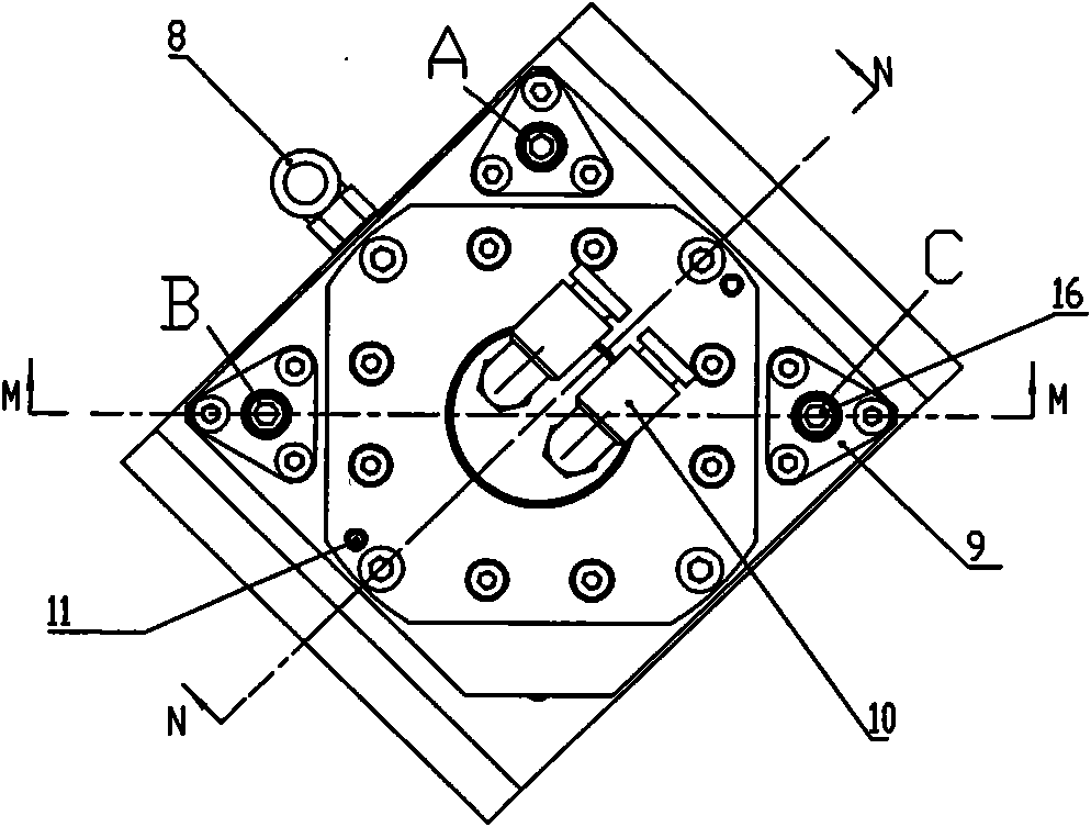
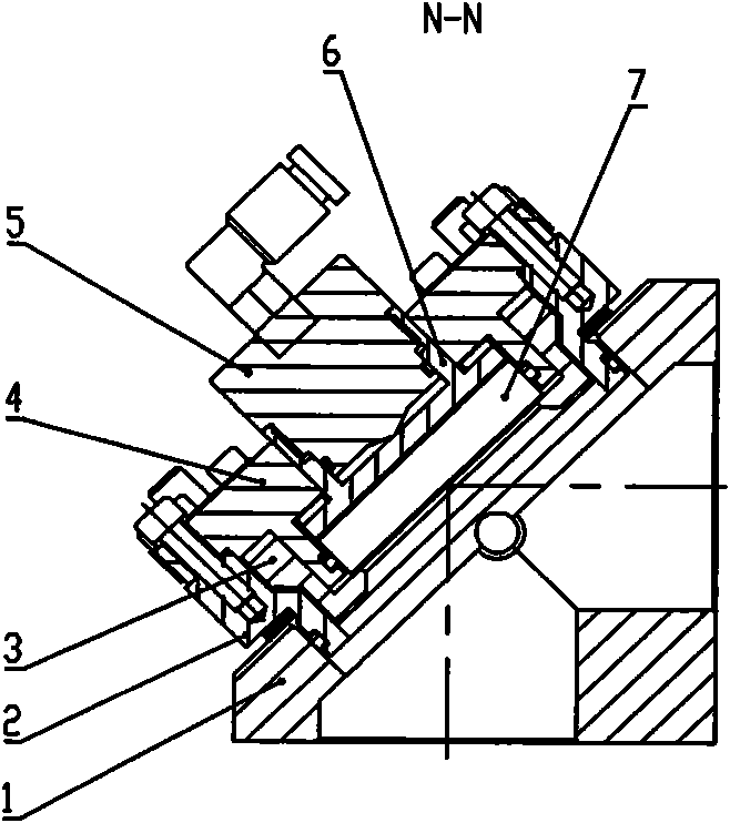
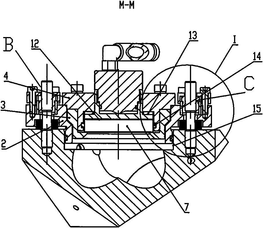
[0026] The present invention as Figure 1-5 As shown, it includes a triangular block-shaped and hollow seat body 1, and two adjacent square surfaces of the seat body 1 are respectively provided with large light-transmitting holes. An adjustment assembly connected to the installation hole 15 with adjustable coaxiality, and an installation assembly detachably connected with the adjustment assembly; the lens 7 is fixedly connected in the installation assembly.

[0027] The adjustment assembly includes a lens adjustment block 2 and three sets of adjustment connectors; the adjustment connectors include a fixed pressure block 9, an adjustment screw 16, an adjustment nut 17 and an adjustment spring 19. In order to further improve the accuracy of connection adjustment, additional Such as Figure 4 The spacer 18 shown; the center of the lens adjustment block 2 is provided with a step circle facing the mounting hole 15 of the seat body, the center of the step circle is provided with an...


PUM


Abstract

The invention relates to a laser mirror assembly. The laser mirror assembly is convenient in adjustment and detection and can realize online detection and debugging. The laser mirror assembly comprises a triangle-shaped and hollow seat body, two adjacent square faces of the seat body are respectively provided with large light holes, the back of the seat body is provided with a mounting hole, the laser mirror assembly also comprises an adjusting assembly which is coaxially and adjustably connected with the mounting hole and a mounting assembly which is connected with the adjusting assembly in a dismountable way; and a lens is fixedly connected in the mounting assembly. In the invention, the adjusting assembly and the mounting assembly are arranged, and the two assemblies are in splittable connecting structures, thus mounting can be directly carried out, the assembly can be polished and polishing test can be carried out only by separating the mounting assembly from the adjusting assembly when the lens is required to be dismounted to be polished during the debugging, replacing and maintenance processes. In the polishing test process, the adjusting assembly is adjusted. After positioning is finished, the mounting assembly provided with a lens is connected, thus the position and angle of a reflected beam mirror surface are not changed after a new lens is mounted and a light path can be directly put into use without adjusting after the new lens is replaced.

Description

technical field [0001] The invention relates to an optical path reflection device, in particular to the improvement of the laser reflection mirror assembly in the numerical control laser processing equipment. Background technique [0002] In order to improve the quality of plate cutting and processing, laser cutting machines are currently widely used. When used in a laser cutting machine, the laser reflector assembly changes the emission direction of the laser beam at the fuselage, beam, and Z-axis. When the laser cutting machine is working normally, the laser beam is required to be located at the center of each reflector to ensure The transmission quality of the beam. However, in long-term use, due to machine vibration and other reasons, some errors in the optical path are inevitable. Therefore, it is necessary to monitor the transmission quality of the speed of light during use, and to adjust in time when an optical path error occurs. In addition, if the lens is old, it...

Claims


Application Information

Patent Timeline
Patent Type & Authority Patents(China)
IPC IPC(8): G02B7/198G02B7/182G02B7/00B23K26/064B23K26/04
Inventor 洪超周鹏飞胡金龙
Owner 江苏扬力数控机床有限公司
Why Eureka
Try Eureka