High frequency electric wire

A wire and high-frequency technology, applied in circuits, inductors, charging stations, etc., can solve problems such as frequency increase, achieve the effect of reducing Joule heat loss, reducing AC resistance and Joule heat loss, and reducing high-frequency AC resistance

Inactive Publication Date: 2011-06-15
SHOWA AIRCRAFT INDUSTRY
View PDF9 Cites 7 Cited by
  • Summary
  • Abstract
  • Description
  • Claims
  • Application Information

AI Technical Summary

Problems solved by technology

[0002] For example, in a non-contact power supply device, a high-frequency AC method is

Method used


Image

  • High frequency electric wire
  • High frequency electric wire
  • High frequency electric wire

Examples


Embodiment Construction

[0047] Modes for carrying out the present invention will be described in detail below.

[0048] First, the outline of the present invention will be described with reference to FIGS. 1 and 2 .

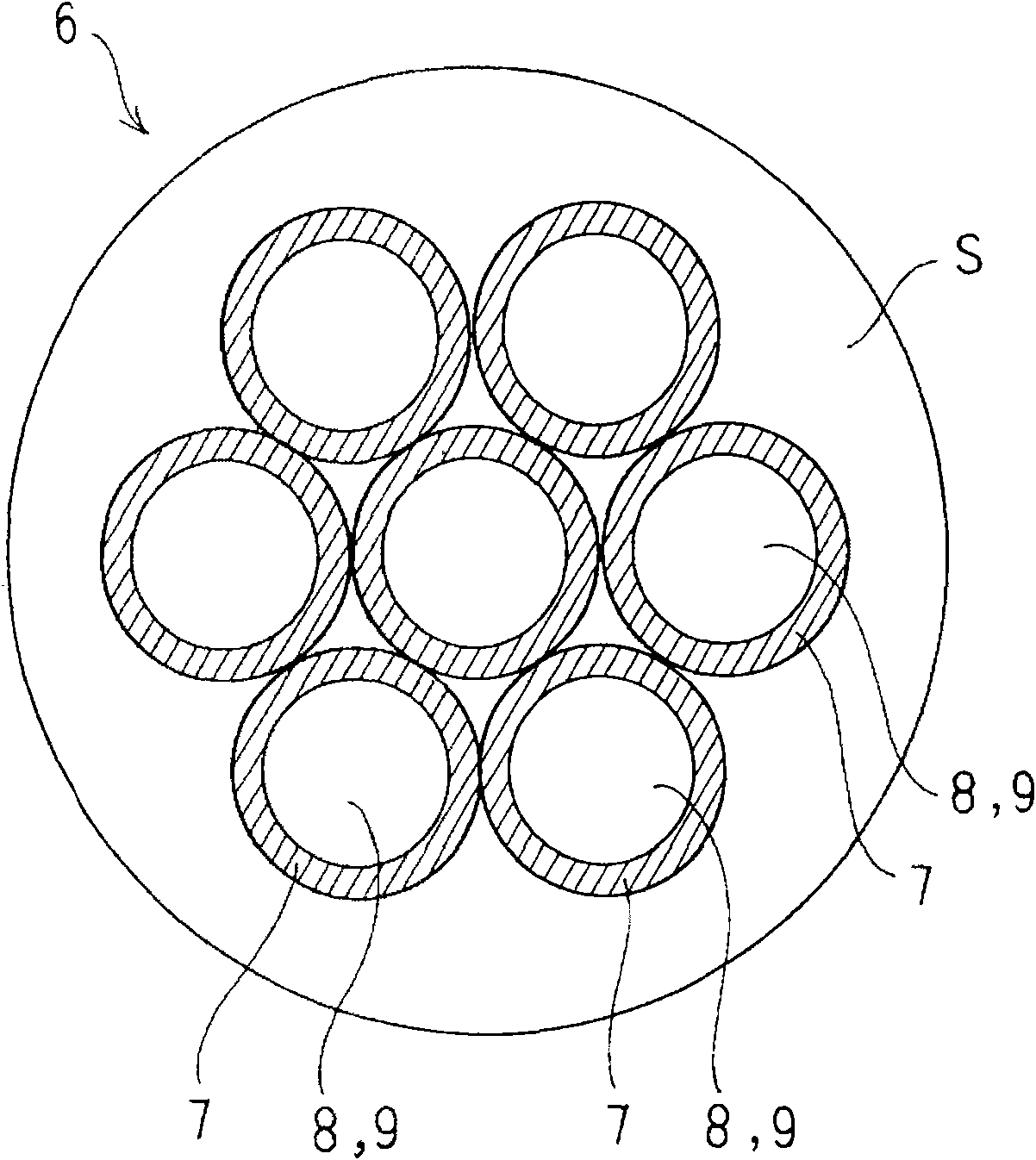
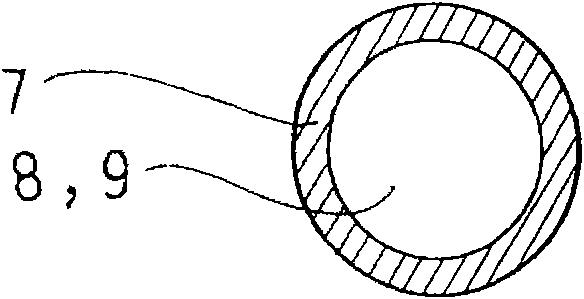
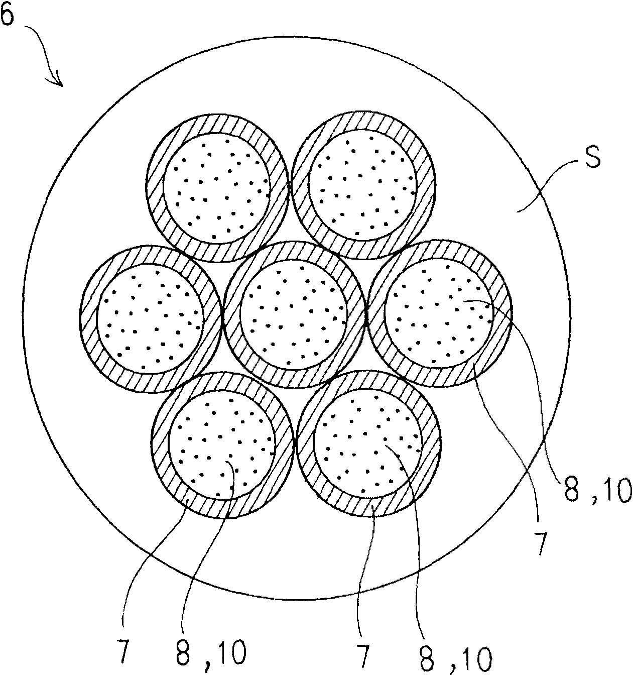
[0049] The high-frequency electric wire 6 of the present invention has a plurality of wires 7 twisted together, and is insulated and covered by an outer sheath S. Furthermore, it is characterized in that the lead wire 7 is formed with a capillary-shaped ultrafine hollow tube structure.

[0050] And, as a representative example, the wire 7 is as Figure 1A , Figure 1B As shown, the hollow part 8 of the extremely thin hollow tube structure becomes an air hole 9, or as Figure 1C , Figure 1D As shown, the hollow portion 8 is filled with an insulating material 10 . In the latter example, the conductive wire 7 has a structure in which a metal conductor is attached to the outer periphery of an extremely fine insulating wire serving as the insulating material 10 by electroplating or vap...


PUM


Abstract

The present invention provides a high frequency electric wire in which, first, the high frequency alternating current resistance can be reduced to decrease a Joule heat loss, thereby improving the frequency characteristics, and, second, the first point can be excellently realized in terms of cost performance. A high frequency electric wire 6 is provided in such a manner that a large number of wires 7 are bundled, twisted and insulated with an outer sheath S. Each wire 7 has an extra-fine hollow pipe structure of a capillary shape. The wire 7 is provided to make its hollow section 8 with the extra-fine hollow pipe structure an air cavity 9 or to cause its hollow section 8 to house an insulating material 10. In the latter case, the wire 7 is provided to cause a metal conductor to adhere to the outer periphery of an extra-fine insulating yarn which serves as the insulating material 10 by plating or vapor- deposition. The electric wire 6 is used as a circuit cable or a coil in a non-contact power feeding device which supplies power based on a mutual induction action of the electromagnetic induction. In this manner, the electric wire 6 fulfills its function to suppress and reduce an increase of the alternating current resistance due to a high frequency alternating current.

Description

technical field [0001] The present invention relates to electric wires for high frequency use. That is, the present invention relates to electric wires used as high-frequency wiring materials, coil materials, or others. Background technique [0002] For example, in a non-contact power supply device, a high-frequency alternating current method is used, but with regard to the high-frequency waves used, the frequency increase is remarkable. [0003] That is, the non-contact power supply device supplies electric power from a fixed power-supply-side coil to a power-receiving-side coil installed in an electric vehicle or the like through an air gap based on mutual induction of electromagnetic induction. In order to meet the needs of large gaps and small and lightweight coils, a high-frequency AC method is adopted. In addition, in view of these needs, high-frequency waves around 20 kHz are currently used, but it is predicted that high-frequency waves of 50 kHz to 100 kHz, or even...

Claims


Application Information

Patent Timeline
IPC IPC(8): H01B7/30H01B5/06H01B5/08B60M7/00H01B7/00H01F38/14
CPCH01B9/006Y02T10/7005Y02T90/14Y02T90/122H01B7/30Y02T10/7088B60L11/182H02J5/005Y02T10/7072B60L53/12Y02T10/70H02J50/12Y02T90/12
Inventor 山本喜多男佐藤刚阿部馨介望月正志冲米田恭之
Owner SHOWA AIRCRAFT INDUSTRY
Why Eureka
Try Eureka