Heat dissipation structure of high-definition vidicon
A high-definition camera and heat dissipation structure technology, applied in image communication, color TV parts, TV system parts, etc., can solve problems such as contact disconnection, CCD chip failure, and CCD chip heat cannot be dissipated in time, to achieve Stable work, avoid the effect of overheating
Inactive Publication Date: 2011-06-15
TIANJIN TIANDY DIGITAL TECH
View PDF5 Cites 13 Cited by
- Summary
- Abstract
- Description
- Claims
- Application Information
AI Technical Summary
Problems solved by technology
In the high-definition camera in the prior art, a high-definition CCD chip is used to convert the image into a video signal. Due to the high resolution of the video, the heat generated by the CCD chip is relatively large during operation, and the CCD chip is surrounded by the shell of the high-definition camera. The interior is separated from the external space, and the heat generated by the CCD chip cannot be dissipated in time, resulting in an excessively high working temperature of the CCD chip
The existing heat dissipation method is generally to fill the inside of the camera housing with heat-conducting adhesive or similar heat-conducting material to conduct the heat of the CCD chip to the housing, but the above-mentioned filler is easy to separate from the CCD chip or the housing in actual use, and the contact is broken. As a result, the heat cannot be conducted in time, and it is easy to cause the CCD chip to fail
Method used
View moreImage
Smart ImageViewing Examples

Examples
Embodiment Construction
Login to View More PUM
 Abstract
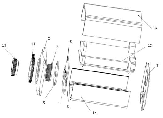
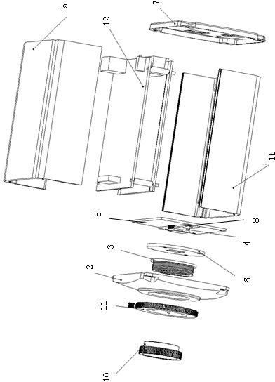
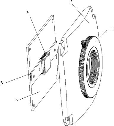
The invention provides a heat dissipation structure of a high-definition vidicon. The vidicon comprises a shell, a vidicon front panel, a CS adapter ring, a charge coupled device (CCD) chip, a CCD circuit board, an optical filter mounting plate, a vidicon mainboard, a vidicon rear panel and a CCD heating panel, wherein the CCD heating panel is of a metal strip structure; the CCD heating panel is inserted into a gap which is fixed between the CCD chip and the CCD circuit board; the back of the CCD chip is closely adhered to the CCD heating panel; and parts extending out of the two ends of the CCD heating panel are adhered to and contacted with the vidicon front panel respectively. Quantity of heat generated by the CCD chip in working can be directly conducted to the vidicon front panel by the CCD heating panel, and then the vidicon front panel performs heat exchange with the outside, so that the quantity of heat generated by the CCD chip can be dissipated outside the shell, thus avoiding the temperature of the CCD chip from being overhigh in the working, thereby ensuring that the high-definition vidicon can stably work in the long-term monitoring operation.
Description
Heat dissipation structure of HD camera technical field The invention relates to the technical field of monitoring cameras, in particular to a heat dissipation structure of a high-definition camera that transmits and radiates heat generated by a CCD chip to the outside in time through a CCD cooling plate, thereby ensuring the normal operation of the CCD chip. Background technique The high-definition camera mentioned in the monitoring field is a monitoring camera that has a high-resolution image acquisition and processing unit, and performs remote data transmission and sending of the collected image data through the network. Usually in the monitoring industry, the concept of high-definition cameras is divided into two types, one is analog high-definition cameras, and the other is digital high-definition cameras. The analog camera is limited by its own performance, and its resolution reaches D1 or 4CIF products (D1 resolution: PAL system 720×576, NTSC system 720×480; 4CIF r...
Claims
Login to View More Application Information
Patent Timeline
 IPC IPC(8): H04N5/225H05K7/20
Inventor 戴林张秋菊
Owner TIANJIN TIANDY DIGITAL TECH
Features
- Generate Ideas
- Intellectual Property
- Life Sciences
- Materials
- Tech Scout
- Unparalleled Data Quality
- Higher Quality Content
- 60% Fewer Hallucinations
Learn More Browse by: Latest US Patents, China's latest patents, Technical Efficacy Thesaurus, Application Domain, Technology Topic, Popular Technical Reports.
© 2025 PatSnap. All rights reserved.Legal|Privacy policy|Modern Slavery Act Transparency Statement|Sitemap|About US| Contact US: help@patsnap.com