Method for shifting the point of machining of a work piece and machine tool

A technology for processing positions and moving workpieces. It is used in metal processing machinery parts, metal processing, automatic control devices, etc. It can solve the problems of increased workspace, low dynamics, and high quality, and achieves low air pollution and high dynamics. , optimize the suction effect

Inactive Publication Date: 2015-06-03
TRUMPF WERKZEUGMASCHINEN GMBH & CO KG
View PDF4 Cites 1 Cited by
  • Summary
  • Abstract
  • Description
  • Claims
  • Application Information

AI Technical Summary

Problems solved by technology

However, increasing the working space by extending the axis, for example the cantilever beam 12, has a number of disadvantages, such as greater mass to be moved, less stiffness and less dynamics

Method used


Image

  • Method for shifting the point of machining of a work piece and machine tool
  • Method for shifting the point of machining of a work piece and machine tool
  • Method for shifting the point of machining of a work piece and machine tool

Examples


Embodiment Construction

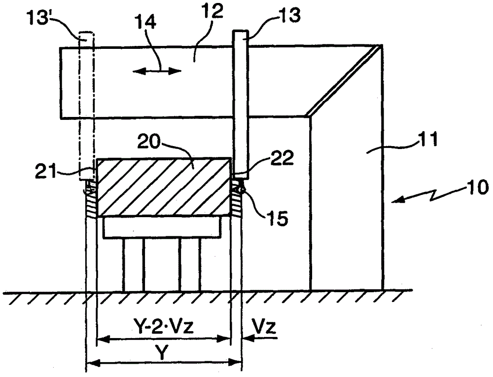
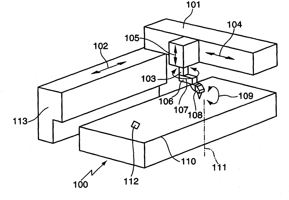
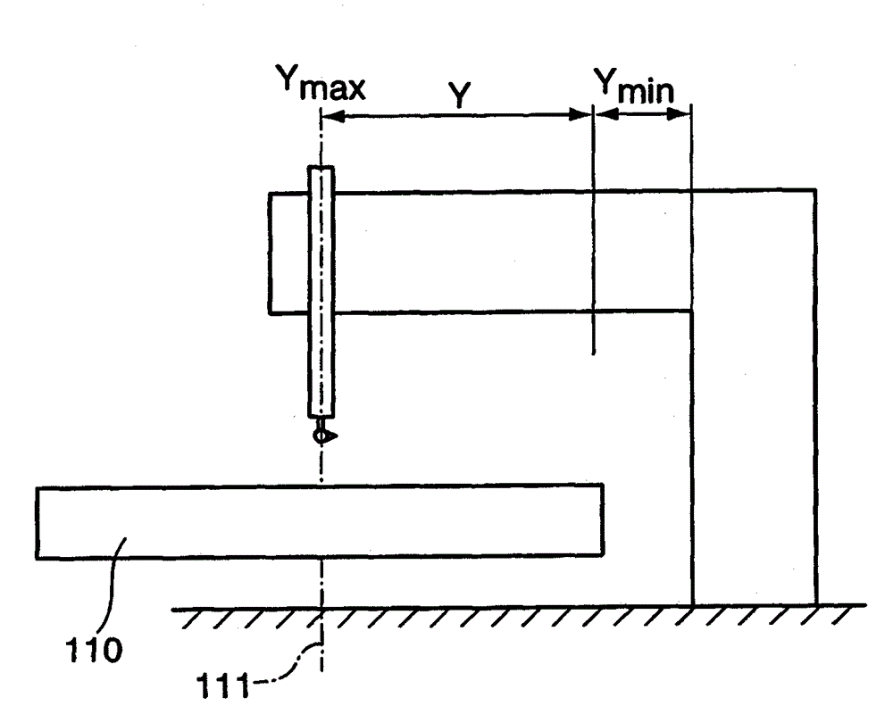
[0036] exist figure 2 A machine tool 100 is shown in which a cantilever beam 101 is movable in an axial direction 102 . The device 103 is movable in the axial direction 104 along the cantilever beam 101 . Device 103 is additionally movable in axial direction 105 . The x, y, z directions of the Cartesian coordinate system are determined by the axial directions 102 , 104 , 105 . Part 106 is rotatable in axial direction 107 . A tool 108 designed as a laser cutting head, which in turn is rotatable in an axial direction 109 , is arranged on the component 106 . The device causing the movement in one of the axial directions 102 , 104 , 105 , 107 or 109 is the tool axis and is responsible for the movement of the tool 108 relative to the workpiece carrier 110 . The workpiece holder 110 is arranged rotatably about a rotation axis 111 . The workpiece holder 110 is in particular arranged to be rotatable. The device that causes the workpiece support 110 to rotate about the axis of r...


PUM


Abstract

In a method for shifting the point of machining (112) of a work piece where machining is being done to the work piece by a tool (108) of a machine tool (100, 300), a. the tool (108) is moved using at least one tool axis; b. the tool (110) is moved using a work piece axis during work piece machining such that the point of machining (112) comes to a work space (yeff xeff) of the tool (108) and / or the point of machining (112) comes to an area near the machine body; wherein c. a more dynamic movement is carried out by the tool axis(es) than by the work piece axis.

Description

technical field [0001] The invention relates to a method for moving a machining location of a workpiece, in which the workpiece is machined with a tool of a machine tool, and to a machine tool, which is used, in particular, for carrying out the method according to the invention. Background technique [0002] It is known that in machine tools the tool can be moved by one or more tool axes, which means a device including a drive which moves the tool in axial direction. The axis direction may be the direction of the translation axis or also the direction of the rotation axis. To move the tool relative to the workpiece, several movements with different orientations can be superimposed, ie the tool is moved via several axes. [0003] The machining of the workpiece can take place in a workspace defined by the tool axis, the workpiece being usually arranged in a fixed position for reasons of simplified clamping technology. In this case, the working space includes all points that ...

Claims


Application Information

Patent Timeline
Patent Type & Authority Patents(China)
IPC IPC(8): B23Q15/00
CPCB23Q15/0075B23Q1/445
Inventor W·瓦登
Owner TRUMPF WERKZEUGMASCHINEN GMBH & CO KG
Why Eureka
Try Eureka