Blade for a turbo device with a vortex-generator

一种涡轮叶片、涡轮机的技术,应用在发动机控制、发动机元件、发动机制造等方向,能够解决难以加工使用时间等问题,达到改善可加工性、可覆层性延长、低效率损失的效果

Inactive Publication Date: 2011-06-15
MTU AERO ENGINES GMBH
View PDF6 Cites 14 Cited by
  • Summary
  • Abstract
  • Description
  • Claims
  • Application Information

AI Technical Summary

Problems solved by technology

But this positive effect also fails to solve the problems of difficult processing and low service life

Method used


Image

  • Blade for a turbo device with a vortex-generator
  • Blade for a turbo device with a vortex-generator
  • Blade for a turbo device with a vortex-generator

Examples


Embodiment Construction

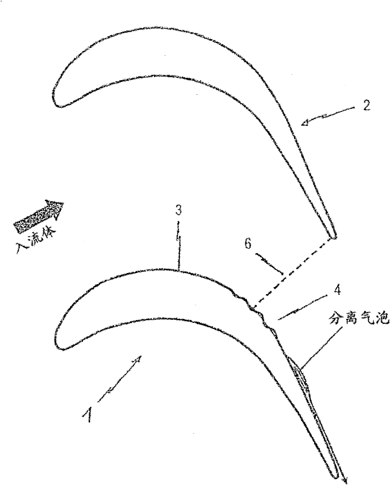
[0028] exist image 3Two adjacent blades 1 , 2 of a turbine are shown in , on their suction-side profiled surface 3 , downstream of the maximum speed, a vortex generator 4 is arranged. In a preferred embodiment, the vortex generator 4 is formed by a plurality of edgeless surface waves, whose wave tails (Wellenrüken) 5 are mainly distributed in the shape of troughs and crests in the blade height direction h, as it is also Figure 4 as shown in. Said wave 4 is also arranged along the blade suction side 3 in such a way that the fluid rises and falls alternately on this wave 4, i.e. the wave 4 is mainly distributed in the direction of the flow (see Figure 4 ) and at least in the blade height direction h according to Figure 4 The core fluid region extends between 20% and 80% of the blade height.

[0029] as by image 3 It can also be seen that the wave 4 has a sinusoidal shape, the maximum amplitude of which is constant in the flow direction. However, it is also possible for...


PUM


Abstract

The invention relates to a blade construction for a turbo device, preferably a blade array of a low-pressure turbine, on the inlet-side profile surface (3) of which a vortex generator (4) is arranged downstream of the speed maximum. The vortex generator is formed by a surface undulation with at least one wave, the wave back of which runs in the form of a wave trough and / or wave peak in the blade vertical direction.

Description

technical field [0001] The invention relates to a blade structure according to the preamble of claim 1 , which has at least partial surface features in the form of vortex generators or swirl generators. Background technique [0002] Such blade structures are used, for example, in rotors and cascades (rotor blades and / or guide blades) of low-pressure turbines of aircraft drives. [0003] The influence of fluids, in particular of the boundary layer close to the surface, by means of vortex generators (also referred to as turbulators) is at least one widely studied subject at the research level. In principle, the boundary layer is produced by the wall friction of the flowing particles and at a distance from the flowed contour wall forms a fluidic bridge between the contour and an ideal fluid which is not adversely affected by wall friction. The thickness of the boundary layer here depends on the Reynolds number. The thickness of the boundary layer increases continuously as the...

Claims


Application Information

Patent Timeline
Patent Type & Authority Applications(China)
IPC IPC(8): F01D5/14
CPCF05D2250/184F05D2270/17F05B2250/182Y02T50/673F01D5/145F05D2250/182F05B2250/184Y02T50/60
Inventor A·菲亚拉J·吉尔
Owner MTU AERO ENGINES GMBH
Why Eureka
Try Eureka