Laser marking method and device based on CCD (Charge Coupled Device) image navigation

A laser marking method and image positioning technology, applied in typewriters, printing, etc., can solve problems such as prohibitive prices for customers, and achieve the effects of convenient use, low cost, and high precision

Inactive Publication Date: 2011-06-22
上海功源电子科技有限公司
View PDF0 Cites 21 Cited by
  • Summary
  • Abstract
  • Description
  • Claims
  • Application Information

AI Technical Summary

Problems solved by technology

[0011] 6. Domestic current equipment manufacturing process precision
[0015] At this stage, there are only a few laser manufacturers, and all of them are foreign lasers. They integrate the CCD and the laser into the same lens, which can greatly improve the accuracy of marking, but the price makes many customers discouraged.

Method used


Image

  • Laser marking method and device based on CCD (Charge Coupled Device) image navigation
  • Laser marking method and device based on CCD (Charge Coupled Device) image navigation

Examples


Embodiment

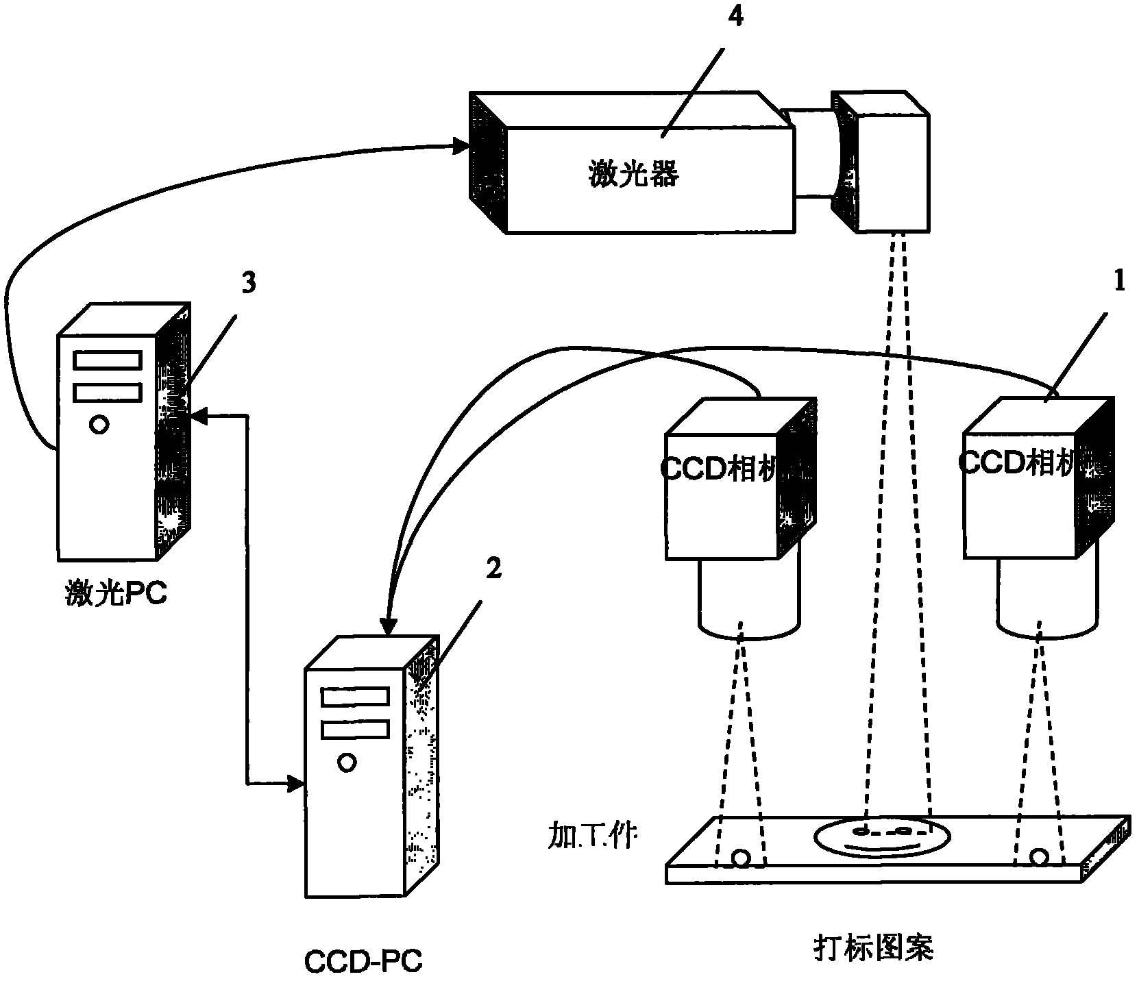
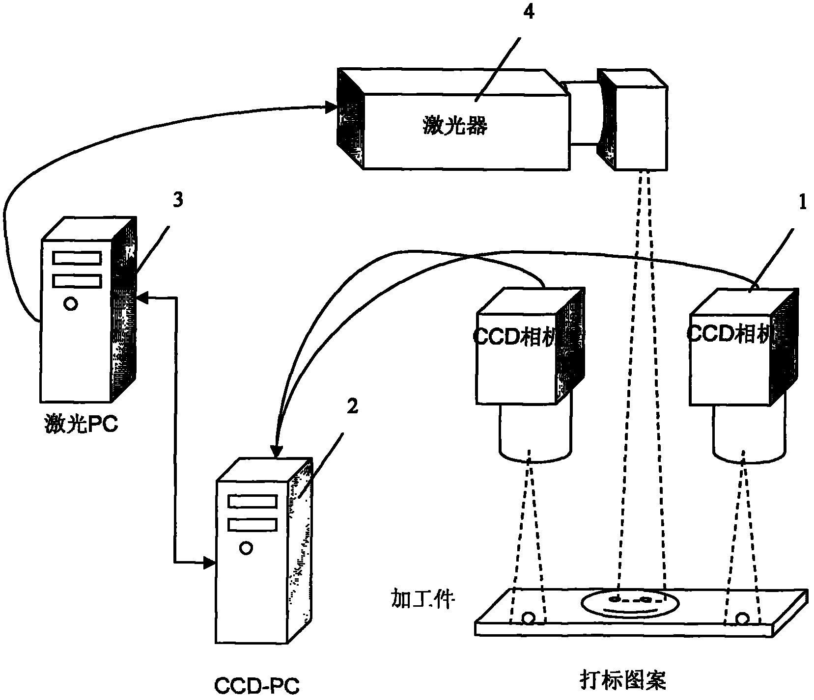
[0032] Such as figure 1 Shown, a kind of laser marking device based on CCD image positioning, this device comprises CCD camera 1, CCD-PC 2, laser PC 3, laser 4, described CCD camera 1, CCD-PC 2, laser PC 3, The lasers 4 are connected sequentially. There are 2 CCD cameras.

[0033] A laser marking method based on CCD image positioning is realized by the following methods:

[0034] 1) Input the product position parameters into the CCD-PC 2, and the CCD-PC 2 checks the position of the marking pattern;

[0035] 2) Put in the product;

[0036] 3) The CCD camera 1 collects and detects the characteristic images of different positions on the left and right of the product respectively, and transmits them to the CCD-PC 2;

[0037] 4) CCD-PC 2 compares the product position parameters set in step 1), calculates by CCD-PC 2, obtains the absolute displacement coordinate value of the product, and transmits this value to laser PC 3;

[0038] 5) The laser PC 3 superimposes the absolute di...


PUM


Abstract

The invention relates to a laser marking method based on CCD (Charge Coupled Device) image navigation, comprising the following steps: 1) inputting a product position parameter into CCD-PC (Personal Computer), correcting a marking pattern position by the CCD-PC; 2) putting a product in; 3) respectively collecting and detecting characteristic images on the left position and the right position of the product by a CCD camera, and transferring the characteristic images to the CCD-PC; 4) comparing the product position parameter set in step 1) by the CCD-PC, calculating by the CCD-PC to obtain the absolute displacement coordinate value of the product, and transmitting the value to a laser PC; 5) overlaying the absolute displacement coordinate value of the product to the marking coordinate valueof a laser; positioning a marking pattern onto the corresponding position of the product; and printing. Compared with the prior art, the laser marking method has the advantages of low cost and the like and is convenient to use.

Description

technical field [0001] The invention relates to a laser marking method and device, in particular to a laser marking method and device based on CCD image positioning. Background technique [0002] Laser marking technology is one of the largest application areas of laser processing. Laser marking is a marking method that uses a high-energy-density laser to locally irradiate the workpiece to vaporize the surface material or undergo a chemical reaction of color change, thereby leaving a permanent mark. Laser marking can print various characters, symbols and patterns, etc., and the character size can range from millimeters to microns, which has special significance for product anti-counterfeiting. [0003] What kind of information the laser can mark is only related to the design content in the computer. As long as the drawing marking system designed in the computer can recognize it, the marking machine can accurately restore the design information on a suitable carrier. Therefo...

Claims


Application Information

Patent Timeline
Patent Type & Authority Applications(China)
IPC IPC(8): B41J3/407
Inventor 卢冬青
Owner 上海功源电子科技有限公司
Why Eureka
Try Eureka