Compression releasing engine braking method and device

An engine brake and release type technology, applied in engine control, engine components, machine/engine, etc., can solve the problems of increasing engine height and weight, inconvenient installation and debugging, poor reliability and durability, etc.

Active Publication Date: 2011-06-22
奚勇
View PDF22 Cites 31 Cited by
  • Summary
  • Abstract
  • Description
  • Claims
  • Application Information

AI Technical Summary

Problems solved by technology

[0016] The object of the present invention is to provide a compression release type engine braking method, which will solve the problems of

Method used


Image

  • Compression releasing engine braking method and device
  • Compression releasing engine braking method and device
  • Compression releasing engine braking method and device

Examples


Embodiment 1

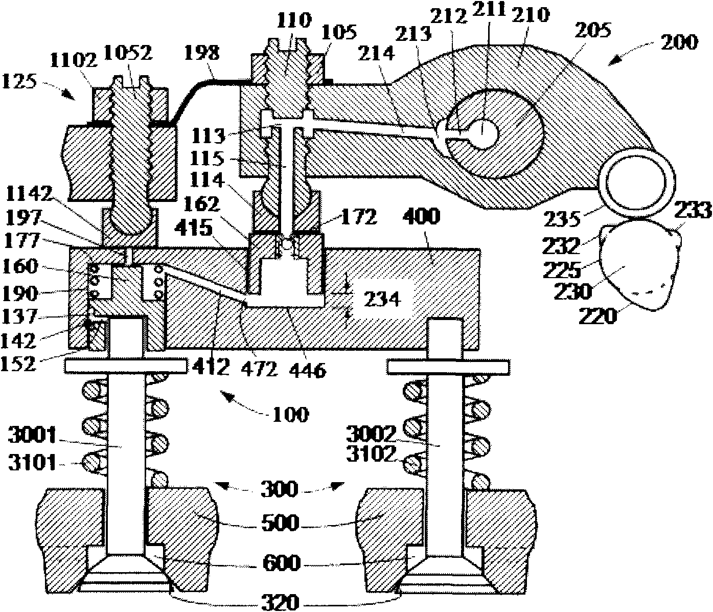
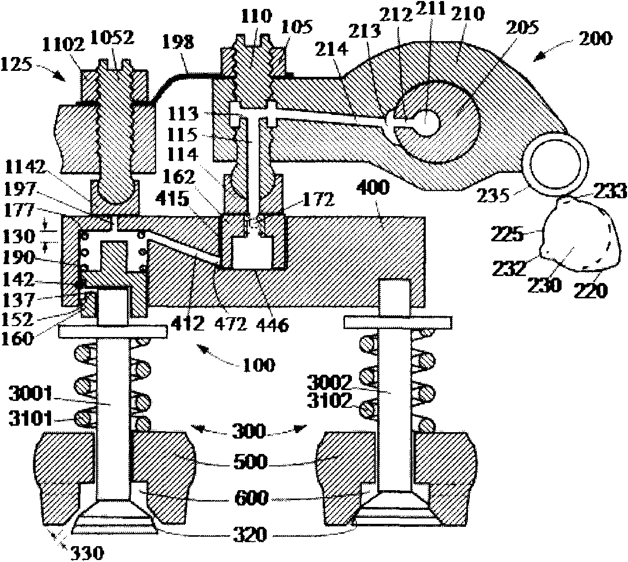
[0082] Such as figure 1 with figure 2 As shown, the cam 230 of the first embodiment of the compression release engine braking device of the present invention is respectively at the position of the inner base circle 225 and the position of the highest lift of the braking boss during braking. figure 1 with figure 2 It includes three main components: the exhaust valve actuator 200, the exhaust valve 300 (including the first exhaust valve 3001 and the second exhaust valve 3002) and the engine brake driving mechanism 100.

[0083] Exhaust valve actuator 200 includes cam 230 , cam follower 235 , rocker arm 210 and valve bridge 400 . Collectively, exhaust valve actuator 200 and exhaust valve 300 may be referred to as an exhaust valve drive train. Usually, one end of the rocker arm 210 (the side close to the valve bridge 400 or the side close to the cam 230 ) is provided with a valve clearance adjustment system. The valve gap adjusting system in this embodiment is composed of a ...

Embodiment 2

[0106] Such as Figure 9 with Figure 10 As shown, the second embodiment of the compression release engine braking device of the present invention has the cam in the position of the inner base circle during non-braking and braking. The difference between this embodiment and the first embodiment is that this embodiment uses a different brake bracket 125 . The brake bracket 125 located above the valve bridge 400 has two main functions: one is to support the valve bridge 400 during engine braking, prevent or limit the upward movement of the valve bridge 400, and close the oil discharge channel above the auxiliary piston hole 190 197, bear the braking load transmitted from the brake exhaust valve 3001; second, in each cycle of engine braking, when the top of the integrated exhaust boss 220 pushes the valve bridge down, the secondary piston hole is opened The oil unloading channel 197 above the 190 unloads the oil, and resets the valve lift curve of the brake exhaust valve 3001. ...


PUM


Abstract

The invention discloses a compression releasing engine braking method and device. A primary piston hole and a secondary piston hole connected with a hydraulic passage are formed in a valve bridge, and a primary piston and a secondary piston in the piston holes are driven by using a braking lug boss of a cam to open an exhaust valve for braking. During braking, the retraction position of the primary piston is kept by using the equal altitude section of the braking cam at the maximum braking lift, the hydraulic passage between the primary piston hole and the secondary piston hole is closed, and the braking load on the secondary piston is transferred to a braking bracket positioned on the valve bridge and is not returned to the primary piston. The primary piston is further driven by using an integrated exhaust lug boss on the cam, the primary piston drives the valve bridge to move and is separated from the braking bracket, and an oil discharge passage in the valve bridge is opened to discharge oil, so that the secondary piston returns to the retraction position, and the braking exhaust door is moved to a closed position. A compression releasing braking mechanism is integrated with a traditional air valve driving chain, and the braking bracket bears the braking load and the weight braking valve lift, so the braking load is reduced and the braking power is increased.

Description

Technical field: [0001] The invention relates to the mechanical field, in particular to the valve driving field of a vehicle engine, in particular to a compression release type engine braking method and device. Background technique: [0002] Engine braking can be classified into compression release type braking and vent type braking. The engine's compression-release brake opens the exhaust valve at the end of the engine piston's compression stroke and closes the exhaust valve at the beginning of the expansion stroke (generally before the exhaust valve normally opens). A precedent for a compression release brake was disclosed in US Patent No. 3,220,392 in 1965 by Cummins. The brake system transmits the mechanical input through the hydraulic circuit to the exhaust valve to open. The hydraulic circuit typically includes a main piston that reciprocates within a main piston bore from a mechanical input to the engine, such as movement of an engine injection cam or movement of an...

Claims


Application Information

Patent Timeline
IPC IPC(8): F01L13/06F01L9/02F02D13/04F01L9/14
CPCF01L1/181F01L1/26F02D13/04F01L13/06
Inventor 杨洲
Owner 奚勇
Why Eureka
Try Eureka