Exhaust gas treatment device

A waste gas treatment device and exhaust system technology, which is applied in the direction of exhaust devices, mufflers, gas passages, etc., and can solve problems such as high loads

Active Publication Date: 2019-06-07
EBERSPACHER EXHAUST TECH GMBH & CO
View PDF9 Cites 0 Cited by
  • Summary
  • Abstract
  • Description
  • Claims
  • Application Information

AI Technical Summary

Problems solved by technology

This results in higher loads on the welded points between the respective pipe and housing

Method used


Image

  • Exhaust gas treatment device
  • Exhaust gas treatment device
  • Exhaust gas treatment device

Examples


Embodiment Construction

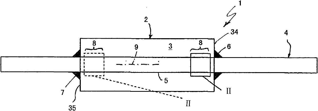
[0028] according to figure 1 , the exhaust gas treatment device 1 comprises a housing 2 which encloses at least one interior space 3 . The exhaust gas treatment device 1 is used for an exhaust system 4 of an internal combustion engine (only partially visible here), which can preferably be accommodated in a road vehicle. The exhaust gas treatment device 1 can be a catalytic converter, for example an oxidation catalytic converter or a NOx storage catalytic converter or an SCR catalytic converter. The exhaust gas treatment device 1 can also be a particle filter, more preferably a soot filter. Furthermore, the exhaust gas treatment device 1 may be a silencer. It also concerns any combination of basic catalytic converters, particulate filters and / or mufflers. Particularly, figure 1 and 4 Only a part of the exhaust gas treatment device 1 is shown in each case.

[0029] figure 1 The exhaust gas treatment device 1 in the exemplary embodiment shown comprises at least one through...


PUM


Abstract

The device has a housing for surrounding an inner area of the device, and a passage tube (5) permeating the inner area and firmly connected with the housing at two fastening points. The passage tube has an expansion compensation section (8) between the fastening points, where a wall of the passage tube has slots (12) and wave-shaped strips (11). The strips are projected opposite to adjacent wall sections (13, 14) of the passage tube. The strips are arranged adjacent to each other in a circumferential direction with respect to a longitudinal axis (9).

Description

technical field [0001] The invention relates to an exhaust gas treatment device for the exhaust system of an internal combustion engine, in particular of a road vehicle. Background technique [0002] The exhaust gas treatment device can be configured, for example, as a catalytic converter or a particle filter or a silencer or comprise any desired combination of these devices. In any case, such an exhaust-gas treatment device usually has a housing which encloses at least one interior space. For certain applications, in particular in the case of silencers, it is necessary to pass at least one through-pipe through the interior space without interruption, wherein the through-pipe is then held in two positions in the housing spaced apart from each other. For example, the through-pipe penetrates the two bases of the spaced-apart housing, which fix the through-pipe transversely. [0003] In order to reduce or avoid the stress between the through pipe and the housing due to the ef...

Claims


Application Information

Patent Timeline
Patent Type & Authority Patents(China)
IPC IPC(8): F01N13/08F01N1/02F01N13/18
CPCF01N13/1811F01N13/08F01N13/1816F01N13/185F01N2470/02F01N2470/24
Inventor 约阿希姆·希尔德布兰德罗尔夫·耶巴辛斯基
Owner EBERSPACHER EXHAUST TECH GMBH & CO
Why Eureka
Try Eureka