
Magnet valve with a valve housing

A technology of solenoid valve and valve shell, applied in the field of solenoid valve, can solve problems such as high cost and so on

Active Publication Date: 2011-06-22
ROBERT BOSCH GMBH
View PDF3 Cites 6 Cited by
  • Summary
  • Abstract
  • Description
  • Claims
  • Application Information

AI Technical Summary

Problems solved by technology

Such valves are only able to work in a set flow direction and are relatively expensive, especially since the described non-return valve is necessary

Method used


Image

  • Magnet valve with a valve housing
  • Magnet valve with a valve housing
  • Magnet valve with a valve housing

Examples


Embodiment Construction

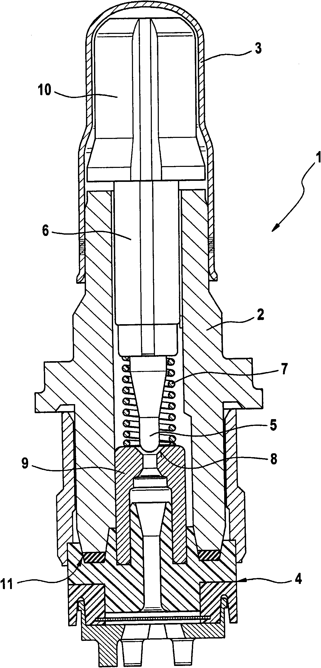
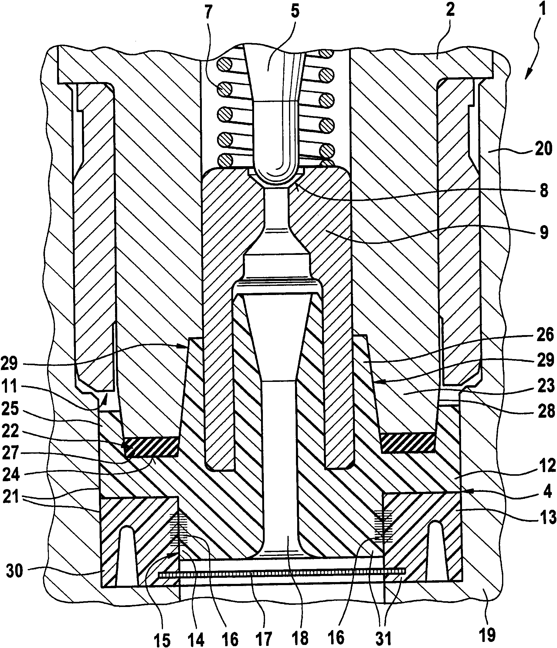
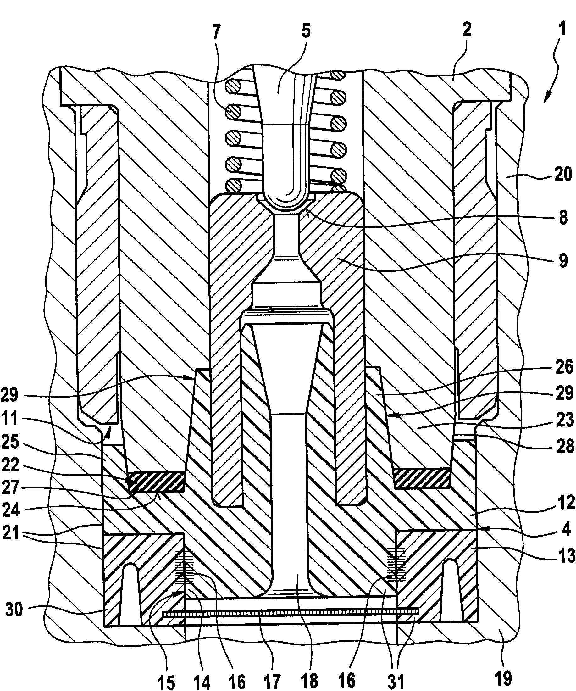
[0019] figure 1 A solenoid valve 1 with a valve housing 2 is shown, which is closed hermetically by a housing cap 3 on the upper side and a sealing body 4 on the lower side. The valve lifter 5 is longitudinally movably supported inside the valve housing 2. The valve lifter is in contact with the armature 6 axially in the direction of the housing cap 3 and the spiral pressure spring surrounding the valve lifter 5 7 works together, wherein the spiral compression spring 7 is supported on the armature 6 on one side, and on the other side is supported on the valve body 9 adjacent to the valve tappet 5 in the axial direction, the valve body There is a valve seat 8 for opening and closing by the valve tappet 5. The valve housing 2 is substantially configured as a hollow cylindrical shape for accommodating an armature 6, a valve tappet 5 connected to the armature, a valve body 9 connected to the valve tappet and having a valve seat 8 and a valve The position of the tappet 5 is opposit...


PUM


Abstract

The invention relates to a magnet valve (1), having a valve housing (2) in which a valve body provided with a valve seat (8) is at least partly disposed. A valve tappet is supported longitudinally displaceably in the valve housing (2) and cooperates with the valve seat (8). A sealing body (4) is provided so as to sealingly close off the valve housing (2) on one of its ends. According to the invention the valve housing (2) has an axial ring rib (22), which sealingly axially engages an annular groove of the sealing body (4).

Description

Technical field [0001] The present invention relates to a solenoid valve with a valve housing. The valve body with a valve seat is at least partially arranged in the valve housing; the solenoid valve also has a longitudinally movable support in the valve body and is connected to the valve seat. A co-acting valve tappet and a sealing body sealingly sealing one end of the valve housing. Background technique [0002] Solenoid valves for isolating the hydraulic circuit and for controlling and connecting the medium in the hydraulic circuit are known. The solenoid valve is configured as an inlet valve that is de-energized to open. The inlet valve has a valve housing (also known as a valve insert). In the valve housing, a valve body with a sealing seat consists of a valve housing The valve tappet that is movable in the middle is open, or is closed by the longitudinal movement of the armature and the valve tappet allocated to the armature when the armature is energized. The valve housi...

Claims


Application Information

Patent Timeline
Patent Type & Authority Applications(China)
IPC IPC(8): F16K31/06F16K27/00
CPCB60T8/363F16K31/0665
Inventor R·舍普N·阿拉策
Owner ROBERT BOSCH GMBH
Learn More