U-shaped channel combined heat pipe receiver

A combined type and receiver technology, applied in the field of U-shaped channel combined heat pipe receiver, can solve the problems of unfavorable Stirling engine operation, increased gas flow resistance, and decreased heat transfer capacity, achieving good sealing and replacement Good thermal effect, enhanced stability effect

Inactive Publication Date: 2011-06-22
ZHEJIANG UNIV
View PDF5 Cites 8 Cited by
  • Summary
  • Abstract
  • Description
  • Claims
  • Application Information

AI Technical Summary

Problems solved by technology

The receiver uses several special-shaped high-temperature heat pipes as the heat transfer unit, which improves the operating efficiency and reliability. The light ratio is low, so there will also be the problem of uneven temperature. At the same time, the outer side of the heat pipe in t

Method used


Image

  • U-shaped channel combined heat pipe receiver
  • U-shaped channel combined heat pipe receiver
  • U-shaped channel combined heat pipe receiver

Examples


Example Embodiment

[0019] The present invention will be further explained with reference to the drawings.

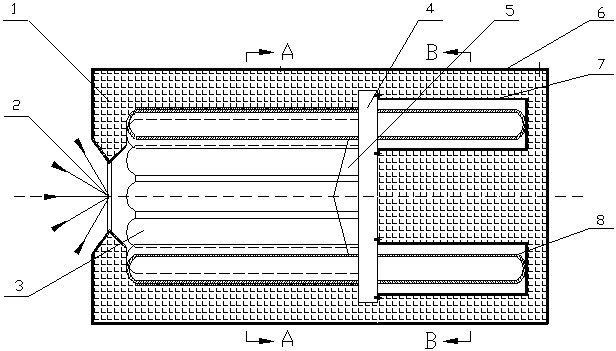
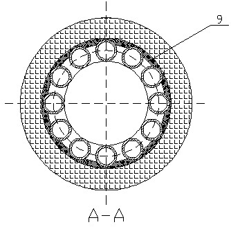
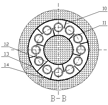
[0020] Such as figure 1 , figure 2 , image 3 As shown, the U-shaped channel combined solar heat pipe receiver includes a high-temperature insulation layer 1, a lighting hole 2, a heat-absorbing section of a heat pipe group 3, a partition plate 4, a diffuse reflection cone 5, an aluminum alloy shell 6, and an annular sleeve 7. , Heat pipe group condensation section 8, annular radiation absorption rib 9, outer wall semi-closed air flow baffle 10, inner wall semi-closed air flow baffle 11, fully enclosed air flow baffle 12, gas inlet 13 and gas outlet 14; heat pipe group suction The heat section 3 and the condensing section 8 of the heat pipe group pass through the partition plate and are evenly arranged in a ring shape. The ring radiation absorption rib 9 is in contact with the heat absorption section 3 of the heat pipe group. The heat absorption section 3 of the heat pipe group, the ring rad...


PUM


Abstract

The invention relates to a U-shaped channel combined heat pipe receiver, which comprises a high-temperature resistant insulating layer, a daylighting hole, a heat pipe group heat absorption section, division plates, a diffuse reflection cone, an aluminum alloy shell, an annular sleeve, a heat pipe group condensation section, an annular radiation absorption rib, an outer wall semi-enclosed airflow baffle plate, an inner wall semi-enclosed airflow baffle plate, a totally-enclosed airflow baffle plate, an air inlet, an air outlet and the like, wherein a high-temperature heat pipe group is centered and arranged annularly and uniformly; the heat pipe group heat absorption section and the heat pipe group condensation section are separated by the division plates; the heat pipe heat absorption section and the annular radiation absorption rib are tightly contacted with each other, and form a U-shaped heat absorption channel together with the diffuse reflection cone; and the heat pipe condensation section is covered by the annular sleeve, and the division plates are internally arranged between adjacent heat pipes to guide air to flow in an S-shaped track. The U-shaped channel combined heat pipe receiver is suitable for a dish-Stirling solar heat generating system with different kinds of power; and compared with the conventional indirect receiver, the U-shaped channel combined heat pipe receiver has the advantages of uniform distribution of heat flow, high heat transfer efficiency, stable system and the like.

Description

technical field [0001] The invention relates to a heat pipe receiver, in particular to a U-shaped channel combined heat pipe receiver. Background technique [0002] Dish-Stirling solar thermal power generation is one of the highest photoelectric conversion efficiency methods in solar thermal power generation technology. It gathers solar radiation into a thermal receiver through a rotating parabolic dish concentrator, and the receiver absorbs the energy and then the The Stirling heat engine realizes the conversion of solar energy into electrical energy. Generally, the power of solar Stirling engines is relatively small, which is suitable for distributed energy utilization and has the potential for large-scale combined grid-connected power generation. In addition, they can also be designed as combined fuel and solar concentrator heating systems, which can use fossil fuels instead of sunlight to continuously generate electricity when there is no sunlight. [0003] The dish so...

Claims


Application Information

Patent Timeline
IPC IPC(8): F24J2/46F24J2/32F24J2/50F24S10/95
CPCY02E10/44F24S10/95F24S20/20
Inventor 帅鸥胡亚才俞自涛阮光正陈健陈欢
Owner ZHEJIANG UNIV
Why Eureka
Try Eureka