Electromagnetic oscillation energy collection device

A technology of oscillating energy and collecting device, applied in electromechanical devices, electrical components, etc., can solve the problems of large magnetic circuit reluctance, small air gap magnetic density, large magnetic leakage, etc., to increase output voltage and output electric power, reduce Small reluctance, reliable operation

Inactive Publication Date: 2011-06-22
ZHEJIANG UNIV
View PDF3 Cites 12 Cited by
  • Summary
  • Abstract
  • Description
  • Claims
  • Application Information

AI Technical Summary

Problems solved by technology

[0003] The existing vibrating energy harvester has the disadvantages of large magnetic circuit reluctance, small air gap magnetic density, air gap magnetic flux direction and coil vibration direction cannot be orthogonal, and large magnetic flux leakage.
This limits the improvement of the efficiency of the electromagnetic vibration energy harvester

Method used


Image

  • Electromagnetic oscillation energy collection device
  • Electromagnetic oscillation energy collection device
  • Electromagnetic oscillation energy collection device

Examples


Embodiment Construction

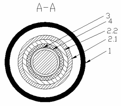
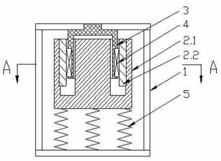
[0013] With reference to the accompanying drawings, the electromagnetic oscillation energy harvesting device includes a housing 1, a mover composed of a magnetically permeable core 2.1 and a permanent magnet 2.2 placed in the housing, an insulated cup-shaped stator 3, a coil winding 4 and a spring 5, and a permeable magnet The core 2.1 is a whole formed by connecting the concentric cylindrical inner core and the bottom of the circular outer core, and has an E-shaped longitudinal section. The permanent magnet 2.2 is located between the inner core and the outer core of the magnetic permeable core 2.1, and is fixed on the outer core. The inner surface of the inner surface, the bottom of the magnetic conductor core 2.1 is connected with one end of the spring 5, the other end of the spring 5 is against the bottom of the housing, the cup-shaped stator 3 is fixed to the inner top surface of the housing 1, and its circular cup is placed In the annular air gap formed by the inner core a...


PUM


Abstract

The invention discloses an electromagnetic oscillation energy collection device. The device comprises a shell, an insulated cup-shaped rotor, a stator, a coil winding and a spring, wherein the rotor is arranged in the shell and consists of a magnetic conductive iron core and a permanent magnet; the magnetic conductive iron core is a whole formed by connecting the bottoms of a cylindrical inner core and an annular outer core in a concentric type, and is provided with an E-shaped longitudinal cross section; the permanent magnet is positioned between the inner core and the outer core of the magnetic conductive iron core and is fixed to the inner surface of the outer core; the bottom of the magnetic conductive iron core is connected with one end of the spring; the other end of the spring is pressed against the bottom of the shell; the cup-shaped stator is fixed with the inner top surface of the shell; the annular cup body of the cup-shaped stator is placed into an annular air gap formed between the inner core and the outer core of the magnetic conductive iron core; the outer surface of the stator is provided with an annular groove along the circumferential direction; and the coil winding is fixed in the annular groove of the stator. The device has a simple structure and reliable operation, and can convert oscillation energy in environment into utilizable electric energy.

Description

technical field [0001] The invention relates to an electromagnetic vibration energy harvester. Background technique [0002] An energy harvester is a miniature power generation device that converts the energy in the surrounding environment into usable electrical energy. It is usually used in conjunction with a supercapacitor or a rechargeable battery to store the collected energy and use it to the outside world when needed. powered by. With the rapid development of low-power integrated circuits, electronic devices consume less and less power. Therefore, conditions are created for the application of micro energy harvesters. Because the service life of the chemical battery is limited, generally 1-2 years, for electronic devices with a long service life, the battery must be replaced during use, and the pollution of the chemical battery is very serious. Therefore, it is of great practical significance to find an alternative method for batteries and choose a method with little...

Claims


Application Information

Patent Timeline
Patent Type & Authority Applications(China)
IPC IPC(8): H02K35/02
Inventor 沈建新王云冲史丹
Owner ZHEJIANG UNIV
Why Eureka
Try Eureka